누리로봇 modebus 프로토콜 매뉴얼
온라인 매뉴얼 URL: https://manuals.nurirobot.info/modbus/index.html
적용대상: BCC6282R - BCC6240R - BCC6021R
1. 개요
BCC6000R Series Brushless DC Motor Driver는 RS485 기반의 Modbus RTU 통신을 지원합니다.
본 매뉴얼은 PLC, HMI, PC 및 기타 Modbus RTU Master 장치에서 BCC6000R Series를 제어하거나 운전 상태를 확인하기 위한 통신 방법을 설명합니다.
지원되는 주요 기능은 다음과 같습니다.
모터 운전 / 정지
정회전 / 역회전
속도 지령
실제 회전속도 확인
Pole Pair 설정 및 확인
Alarm Code 확인
가속/감속 관련 Parameter 설정
Driver 상태 확인
모델별 추가 Parameter 설정
세 모델 모두 Modbus RTU와 Function Code 0x03, 0x06을 사용하지만 Register Address와 통신 설정은 서로 다릅니다. 따라서 다른 모델의 Register Address를 그대로 사용해서는 안 됩니다.
2. 모델별 통신 사양
통합 매뉴얼에서 가장 먼저 아래 비교표를 넣는 것이 좋습니다.
항목 |
BCC6282R |
BCC6240R |
BCC6021R |
|---|---|---|---|
Protocol |
Modbus RTU |
Modbus RTU |
Modbus RTU |
Physical Layer |
RS485 |
RS485 |
RS485 |
통신 방식 |
2-wire |
2-wire |
2-wire |
Connector |
RJ45 / Terminal |
RJ45 |
RJ12 |
기본 Baud Rate |
9600 bps |
115200 bps |
9600 bps |
Baud 변경 |
미지원 |
미지원 |
9600 / 14400 / 19200 |
Data Bit |
8 bit |
8 bit |
8 bit |
Stop Bit |
1 |
1 |
1 |
CRC |
CRC-16/Modbus |
CRC-16/Modbus |
CRC-16/Modbus |
Read |
|
|
|
Write Single |
|
|
|
Slave ID 설정 |
DIP SW |
Register |
DIP SW |
Broadcast |
지원 |
지원 |
지원 |
RS485 제어 활성화 |
|
|
0x0019 |
BCC6240R은 RJ45 기반 RS485, 115200 bps, 8-bit, 1 stop bit이며 통신 주소는 통신을 통해 설정하도록 되어 있습니다. BCC6021R은 Baud Rate Register를 통해 9600/14400/19200을 선택할 수 있습니다.
3. RS485 배선
3.1 BCC6282R
BCC6282R은 RS485 통신용으로 RJ45와 Plug-in Terminal 두 종류의 인터페이스를 제공합니다.
기본 RS485 신호:
A
B
GND
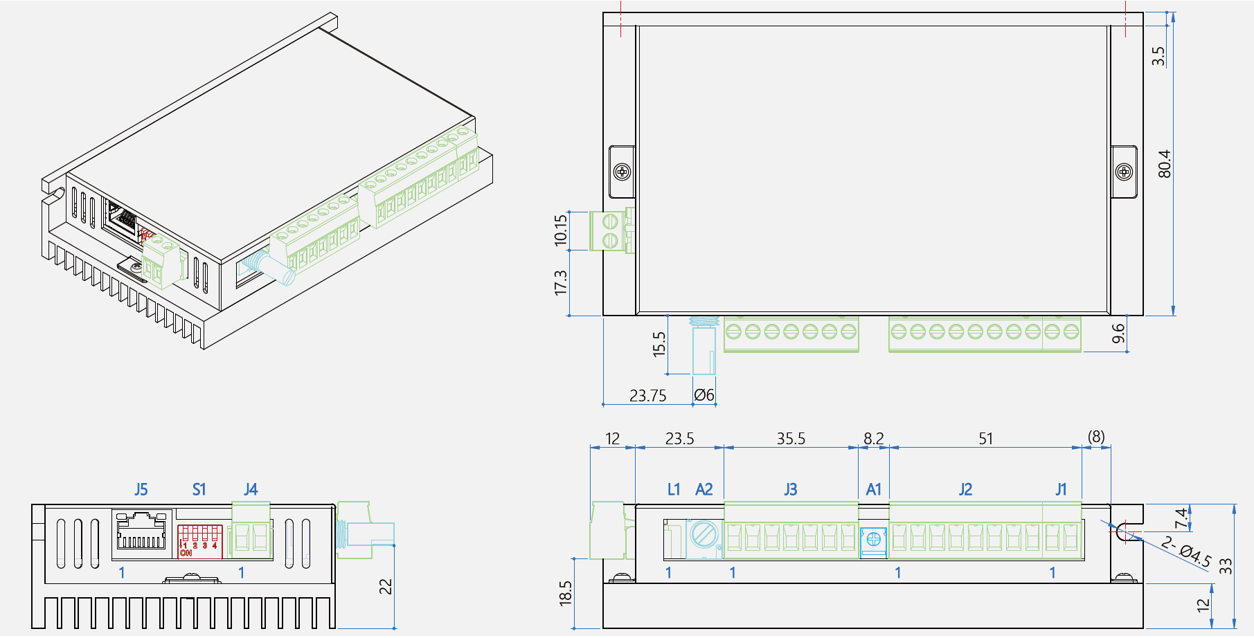
J5(RJ45)에는 추가로 3.3V가 존재하지만 일반적인 RS485 통신에는 A, B, GND를 사용합니다.
3.2 BCC6240R
BCC6240R은 RJ45 Connector를 사용합니다.
통신에 사용하는 신호는:
A
B
GND
입니다.
120 Ω 종단저항은 외부에서 연결하시기 바랍니다.
3.3 BCC6021R
BCC6021R은 RJ12 Connector를 사용합니다.
따라서 BCC6282R / BCC6240R의 RJ45 통신 케이블과 물리적으로 호환되지 않습니다.
4. Slave Address 설정
4.1 BCC6282R
BCC6282R은 DIP Switch SW1~SW3으로 Slave Address를 설정합니다.
SW3 |
SW2 |
SW1 |
Slave Address |
|---|---|---|---|
0 |
0 |
0 |
Broadcast |
0 |
0 |
1 |
1 |
0 |
1 |
0 |
2 |
0 |
1 |
1 |
3 |
1 |
0 |
0 |
4 |
1 |
0 |
1 |
5 |
1 |
1 |
0 |
6 |
1 |
1 |
1 |
7 |
SW4는 기본 제품에서 120 Ω RS485 종단저항 연결용으로 사용됩니다.
4.2 BCC6240R
BCC6240R은 Slave Address를 DIP Switch가 아닌 Register ``0x00A6`` 으로 설정합니다.
Parameter |
Register |
Range |
Default |
|---|---|---|---|
Slave Address |
|
1~247 |
1 |
4.3 BCC6021R
BCC6021R은 DIP Switch를 사용하여 Slave Address를 선택합니다.
다만 이 제품의 DIP Switch는 다단속도 기능에서도 사용되므로, 다단속도 설정 여부에 따라 DIP Switch 기능이 달라집니다.
NOTICEBCC6021R의 DIP Switch는 Slave Address 설정과 Multi-speed 선택에 사용될 수 있습니다. Multi-speed 기능을 사용하는 경우 DIP Switch의 기능이 일반 Slave Address Mode와 다릅니다.
5. Modbus RTU Frame
BCC6000R Series는 아래 두 Function Code를 기본적으로 사용합니다.
0x03 — Read Holding Registers
Master → Driver:
Slave ID | 03 | Start Address Hi | Start Address Lo |
Quantity Hi | Quantity Lo | CRC Lo | CRC Hi
Driver → Master:
Slave ID | 03 | Byte Count | Data... | CRC Lo | CRC Hi
0x06 — Write Single Holding Register
Master → Driver:
Slave ID | 06 | Register Hi | Register Lo |
Data Hi | Data Lo | CRC Lo | CRC Hi
정상적으로 처리되는 경우 대부분의 Write 명령은 동일 Frame을 응답합니다.
세 제품 모두 0x03과 0x06을 사용하며 CRC-16/Modbus를 적용하고 있습니다.
6. 핵심 Register 비교
기능 |
BCC6282R |
BCC6240R |
BCC6021R |
|---|---|---|---|
운전 제어 |
|
|
|
속도 지령 |
|
|
|
실제 속도 |
|
|
|
Pole Pair |
|
|
|
Alarm Code |
|
|
|
가감속 시간 |
|
|
|
Maximum Speed |
|
|
|
통신 제어 설정 |
|
|
|
Baud Rate |
고정 |
고정 |
|
PID P |
|
||
PID I |
|
||
Open/Closed Loop |
|
||
감속비 |
|
||
설정저장 |
|
|
|
공장초기화 |
|
|
|
BCC6021R은 BCC6282R/BCC6240R과 Register 체계가 완전히 다르고, PID, Open/Closed Loop, 감속비 등의 추가 Parameter를 가지고 있습니다.
7. 모델별 통신 제어 활성화
BCC6282R
통신으로 Driver를 제어하기 전에:
Register 0x00B6 = 1
을 Write해야 합니다.
0= RS485 Control Disable1= RS485 Control Enable
0인 경우 다른 Register를 읽을 수는 있지만 0x00B6을 제외한 다른 Write Register를 쓸 수 없습니다.
BCC6240R
BCC6240R도:
0x00B6 = 1
로 Communication Control을 Enable합니다.
중요한 점은 이 값이 저장되지 않는다는 것입니다.
따라서 전원을 다시 켜면 Communication Status가 Disable 상태로 돌아가므로, PLC 프로그램에서 초기화 시 다음 명령을 보내는 구조가 좋습니다.
Power ON
   ↓
Communication Established
   ↓
Write 0x00B6 = 1
   ↓
Set Speed
   ↓
RUN
BCC6021R
BCC6021R은 방식이 다릅니다.
Start/Stop 및 방향 제어 방법:
0x0007
0= Terminal + RS485, Terminal 우선1= Terminal Control2= RS485 Control
그리고 Speed Control Source는:
0x0019
0= Analog Speed Control1= Communication Speed Setting
입니다.
따라서 완전한 Modbus 제어를 하려면 기본적으로:
0x0007 = 2
0x0019 = 1
로 설정하는 구성으로 설명하는 것이 가장 이해하기 쉽습니다.
8. 모델별 Quick Start
본 장에서는 BCC6000R Series를 Modbus RTU를 이용하여 운전하기 위한 최소 설정 절차를 설명합니다.
아래 예제는 다음 조건을 기준으로 합니다.
항목 |
설정값 |
|---|---|
Slave Address |
|
Function Code |
|
목표 회전속도 |
|
1100 rpm HEX |
|
CRC |
CRC-16/Modbus |
CRC 전송 순서 |
Low Byte → High Byte |
모터를 최초로 운전할 때에는 부하를 분리하거나 안전하게 회전할 수 있는 상태에서 시험하십시오. 모터의 U/V/W 및 Hall 배선, 전원전압, Pole 설정이 실제 모터와 일치하는지 먼저 확인해야 합니다.
8.1 BCC6282R Quick Start
8.1.1 통신 설정
BCC6282R은 RS485 기반 Modbus RTU를 사용하며 기본 통신 조건은 다음과 같습니다.
항목 |
설정 |
|---|---|
Baud Rate |
|
Data Bit |
|
Stop Bit |
|
Parity |
None |
Mode |
Modbus RTU |
Slave Address |
DIP Switch |
Read |
|
Write |
|
Slave Address는 DIP Switch로 설정합니다. 본 예제에서는 Slave Address를 1로 설정한 상태를 기준으로 합니다.
8.1.2 RS485 통신 연결 확인
전원을 인가한 후 먼저 Read 명령을 사용하여 Driver와 정상적으로 통신되는지 확인합니다.
예를 들어 Feedback Speed Register 0x005F를 읽습니다.
TX : 01 03 00 5F 00 01 B4 18
정상적으로 통신되는 경우 Driver는 다음 형식으로 응답합니다.
RX : 01 03 02 XX XX CRC_L CRC_H
예에서는 다음과 같이 응답하며 0x0248 = 584 rpm입니다.
TX : 01 03 00 5F 00 01 B4 18
RX : 01 03 02 02 48 B9 12
BCC6282R은 Feedback Speed를 0x005F, Alarm Code를 0x0076에서 읽습니다.
8.1.3 RS485 Control 활성화
BCC6282R은 전원 투입 직후 기본적으로 RS485 Write Control이 비활성 상태입니다.
Modbus를 사용하여 속도, 운전상태 및 기타 Parameter를 변경하려면 먼저 다음 Register를 설정해야 합니다.
Register : 0x00B6
Value    : 1
Function : RS485 Control Enable
통신 프레임:
TX : 01 06 00 B6 00 01 A9 EC
RX : 01 06 00 B6 00 01 A9 EC
0x00B6 = 0인 경우 Holding Register를 읽을 수는 있지만 0x00B6을 제외한 다른 Write Register를 변경할 수 없습니다. 0x00B6 = 1이면 Read/Write가 허용됩니다. 이 Register는 저장되지 않으며 기본값은 0으로 정의되어 있습니다.
따라서 PLC 또는 HMI에서는 전원 투입 후 초기화 절차에서 ``0x00B6 = 1``을 전송하는 것을 권장합니다.
8.1.4 목표속도 설정
목표속도는 0x0056에 rpm 단위로 Write합니다.
1100 rpm은 16진수로:
1100(dec) = 0x044C
입니다.
Register : 0x0056
Value    : 0x044C
Speed    : 1100 rpm
통신 프레임:
TX : 01 06 00 56 04 4C 6A EF
RX : 01 06 00 56 04 4C 6A EF
RS485 Control이 비활성화된 상태에서 같은 Write를 시도하면 Exception Response 01 86 FF 02 20을 반환합니다.
8.1.5 회전방향 설정
BCC6282R에서는 회전방향을 0x006D로 제어합니다.
Forward 명령은 다음과 같습니다.
Register : 0x006D
Value    : 1
Function : Forward
TX : 01 06 00 6D 00 01 D9 D7
RX : 01 06 00 6D 00 01 D9 D7
8.1.6 Motor Enable
다음 명령을 Motor Enable로 사용합니다.
Register : 0x0066
Value    : 1
TX : 01 06 00 66 00 01 A8 15
RX : 01 06 00 66 00 01 A8 15
따라서 기본적인 운전 순서는 다음과 같습니다.
Power ON
   ↓
RS485 Communication Check
   ↓
0x00B6 = 1     RS485 Control Enable
   ↓
0x0056 = 1100  Speed Command
   ↓
0x006D = 1     Forward
   ↓
0x0066 = 1     Enable
   ↓
Motor Run
8.1.7 실제 속도 확인
운전 후 0x005F를 주기적으로 읽어 실제 Feedback Speed를 확인할 수 있습니다.
TX : 01 03 00 5F 00 01 B4 18
응답 Data가 예를 들어:
02 48
이면:
0x0248 = 584 rpm
입니다.
8.1.8 Alarm 확인
Alarm Code는 0x0076에서 읽습니다.
TX : 01 03 00 76 00 01 65 D0
정상상태 예:
RX : 01 03 02 00 00 B8 44
즉,
Alarm Code = 0
입니다.
8.1.9 BCC6282R 운전 순서 요약
Step |
Register |
Value |
Function |
|---|---|---|---|
1 |
|
Read |
통신 확인 |
2 |
|
|
RS485 Control Enable |
3 |
|
|
목표속도 1100 rpm |
4 |
|
|
Forward |
5 |
|
|
Motor Enable |
6 |
|
Read |
Feedback Speed |
7 |
|
Read |
Alarm 확인 |
8.2 BCC6240R Quick Start
BCC6240R은 BCC6282R과 일부 Register Address가 동일하지만 Motor Control 구조가 다릅니다.
특히 BCC6240R에서는 0x0066 하나를 이용하여 Stop, Forward, Reverse 및 Brake를 제어합니다. Register Map은 0 = Stop, 1 = Forward, 2 = Reverse, 3 = Brake로 정의하고 있습니다.
8.2.1 통신 설정
항목 |
설정 |
|---|---|
Baud Rate |
|
Data Bit |
|
Stop Bit |
|
Modbus Mode |
RTU |
CRC |
CRC-16/Modbus |
Slave Address 기본값 |
|
Slave Address Register |
|
Read |
|
Write |
|
Slave Address의 기본값은 1이며 0x00A6을 통해 1~247 범위에서 변경할 수 있습니다.
8.2.2 통신 확인
Feedback Speed를 읽어 통신상태를 확인합니다.
TX : 01 03 00 5F 00 01 B4 18
RX : 01 03 02 02 48 B9 12
8.2.3 Communication Control Enable
Modbus Write Control을 사용하려면:
0x00B6 = 1
로 설정합니다.
TX : 01 06 00 B6 00 01 A9 EC
RX : 01 06 00 B6 00 01 A9 EC
0x00B6의 의미는 다음과 같습니다.
Value |
Description |
|---|---|
|
Communication Disable |
|
Communication Enable |
BCC6240R에서는 이 값이 저장되지 않습니다. 따라서 전원을 다시 투입할 때마다 ``0x00B6 = 1``을 다시 전송해야 합니다.
8.2.4 목표속도 설정
목표속도는 0x0056에 rpm 단위로 설정합니다.
1100 rpm:
0x0056 = 0x044C
통신 프레임:
TX : 01 06 00 56 04 4C 6A EF
RX : 01 06 00 56 04 4C 6A EF
8.2.5 정회전 운전
BCC6240R에서는 Motor Control Register 0x0066을 사용합니다.
0x0066 = 1 : Forward
TX : 01 06 00 66 00 01 A8 15
RX : 01 06 00 66 00 01 A8 15
따라서 BCC6240R의 기본 운전순서는:
Power ON
   ↓
RS485 Communication Check
   ↓
0x00B6 = 1       Communication Enable
   ↓
0x0056 = 1100    Speed = 1100 rpm
   ↓
0x0066 = 1       Forward
   ↓
Motor Run
입니다.
8.2.6 역회전
0x0066 = 2
로 설정합니다.
Value |
Motor Command |
|---|---|
|
Stop |
|
Forward |
|
Reverse |
|
Brake |
Motor가 회전 중인 상태에서 즉시 방향을 변경하면 기계계 및 Driver에 큰 부하가 발생할 수 있으므로, 실제 장비에서는 먼저 정지한 후 방향을 변경하는 운전 Sequence를 권장합니다.
8.2.7 정지
일반 정지는:
0x0066 = 0
입니다.
Slave Address 1 기준 Frame은:
TX : 01 06 00 66 00 00 69 D5
정상 처리 시 Function 0x06 특성에 따라 동일 Frame을 응답합니다.
RX : 01 06 00 66 00 00 69 D5
위 CRC 포함 Frame은 Register 정의에 따라 계산한 예입니다.
8.2.8 실제속도 및 Alarm 확인
Feedback Speed:
Register : 0x005F
Function : 0x03
TX : 01 03 00 5F 00 01 B4 18
Alarm Code:
Register : 0x0076
Function : 0x03
TX : 01 03 00 76 00 01 65 D0
BCC6240R은 별도로 0x0000부터 연속 Read가 가능한 Access Address 체계도 제공하지만 Quick Start에서는 호환성과 가독성을 위해 개별 Address 0x005F, 0x0076을 사용합니다.
8.2.9 BCC6240R 운전 순서 요약
Step |
Register |
Value |
Function |
|---|---|---|---|
1 |
|
Read |
통신 확인 |
2 |
|
|
Communication Enable |
3 |
|
|
Target Speed |
4 |
|
|
Forward |
5 |
|
Read |
Feedback Speed |
6 |
|
Read |
Alarm 확인 |
7 |
|
|
Stop |
전원 재투입 시 Step 2의 ``0x00B6 = 1``을 반드시 다시 실행해야 합니다.
8.3 BCC6021R Quick Start
BCC6021R은 BCC6282R 및 BCC6240R과 제어방식이 다릅니다.
BCC6021R에서는 운전/방향의 제어권과 속도 지령 Source를 서로 다른 Register로 설정합니다.
기능 |
Register |
Modbus 전용 설정 |
|---|---|---|
Start/Stop & Direction Control |
|
|
Speed Command Source |
|
|
0x0007 = 2는 Start/Stop 및 Forward/Reverse를 RS485가 제어하도록 선택하고, 0x0019 = 1은 속도 지령값을 Communication에서 받도록 선택합니다. 따라서 BCC6021R을 Modbus RTU만으로 완전히 제어하려면 두 설정을 모두 확인해야 합니다.
8.3.1 통신 설정
BCC6021R의 기본 통신 조건은 다음과 같습니다.
항목 |
기본 설정 |
|---|---|
Baud Rate |
|
Data Bit |
|
Stop Bit |
|
Parity |
None |
Protocol |
Modbus RTU |
Slave Address |
DIP Switch |
Read |
|
Write |
|
Baud Rate는 0x0006을 통해 변경할 수 있습니다.
|
Baud Rate |
|---|---|
|
9600 |
|
14400 |
|
19200 |
기본값은 0, 즉 9600 bps입니다.
8.3.2 통신 확인
Feedback Speed Register 0x0009를 읽습니다.
TX : 01 03 00 09 00 01 54 08
RX : 01 03 02 03 17 F8 BA
Feedback Speed는 0x0009에서 rpm 단위로 읽으며 이 값은 Gear Reduction Ratio 설정의 영향을 받습니다.
8.3.3 모터 정지 상태 확인
0x0019 Speed Control Mode는 모터 운전 중 변경하지 않아야 합니다. 0x0019 변경 전에 모터를 정지하세요.
따라서 처음 설정할 때에는 모터가 실제로 정지되어 있는 것을 확인한 후 다음 설정을 수행하십시오.
8.3.4 속도 지령 Source를 Communication으로 설정
Register : 0x0019
Value    : 1
의미:
0 = Analog Speed Control
1 = Communication Setting
Slave Address 1 기준 명령 예:
TX : 01 06 00 19 00 01 99 CD
RX : 01 06 00 19 00 01 99 CD
0x0019 = 0인 경우 속도 지령 Source는 Analog 입력이며, On-board RV가 SV 입력보다 높은 우선순위를 가집니다. Modbus에서 0x0001에 속도값을 Write하여 운전하려면 0x0019 = 1로 설정해야 합니다.
8.3.5 Run/Stop 및 방향 제어권을 RS485로 설정
Register : 0x0007
Value    : 2
0x0007의 설정은 다음과 같습니다.
Value |
Control Method |
|---|---|
|
Terminal + RS485, Terminal 우선 |
|
Terminal Control |
|
RS485 Communication Control |
Slave Address 1 기준 명령 예:
TX : 01 06 00 07 00 02 B9 CA
RX : 01 06 00 07 00 02 B9 CA
따라서 BCC6021R의 완전한 Modbus Control 설정은:
0x0019 = 1    Speed Source = Communication
0x0007 = 2    Run/Direction Control = RS485
입니다.
8.3.6 목표속도 설정
BCC6021R의 속도지령 Register는:
0x0001
입니다.
1100 rpm을 설정하면:
0x0001 = 0x044C
통신 프레임:
TX : 01 06 00 01 04 4C DB 3F
RX : 01 06 00 01 04 4C DB 3F
8.3.7 정회전 운전
Motor Command Register는:
0x0000
입니다.
동작은 다음과 같습니다.
Value |
Command |
|---|---|
|
Forward |
|
Reverse |
|
Stop |
|
Clear Alarm |
정회전:
0x0000 = 0
Slave Address 1 기준 명령 예:
TX : 01 06 00 00 00 00 89 CA
RX : 01 06 00 00 00 00 89 CA
0x0000 = 0이 Forward라는 정의는 BCC6021R Register Map에 명시되어 있습니다.
8.3.8 역회전
0x0000 = 1
TX : 01 06 00 00 00 01 48 0A
RX : 01 06 00 00 00 01 48 0A
방향을 변경할 때에는 기계적 충격을 줄이기 위해 모터를 먼저 정지시킨 후 방향을 변경하십시오.
8.3.9 정지
모터 정지는:
0x0000 = 2
입니다.
TX : 01 06 00 00 00 02 08 0B
RX : 01 06 00 00 00 02 08 0B
정지 동작은 0x0005 Stop Mode 설정의 영향을 받습니다.
0 = Free Stop
1 = Brake Stop
2 = Deceleration Stop
8.3.10 실제속도 확인
Feedback Speed:
Register : 0x0009
TX : 01 03 00 09 00 01 54 08
이 Register의 Feedback Speed는 Gear Ratio 0x0015 설정의 영향을 받습니다.
8.3.11 Alarm 확인
Alarm Code는 0x0012에서 읽습니다.
TX : 01 03 00 12 00 01 24 0F
정상상태 예:
RX : 01 03 02 00 00 B8 44
즉:
Alarm Code = 0
Alarm을 통신으로 Clear할 경우:
0x0000 = 3
을 사용합니다.
8.3.12 BCC6021R 운전 순서 요약
최초 Modbus 전용 제어 설정
Power ON
   ↓
RS485 Communication Check
   ↓
Motor Stop 확인
   ↓
0x0019 = 1
Speed Source = Communication
   ↓
0x0007 = 2
Run/Direction = RS485
   ↓
0x0001 = 1100
Target Speed = 1100 rpm
   ↓
0x0000 = 0
Forward
   ↓
Motor Run
운전 중에는:
0x0009 → Feedback Speed Read
0x0012 → Alarm Code Read
를 주기적으로 확인할 수 있습니다.
정지할 때에는:
0x0000 = 2
를 전송합니다.
8.4 3모델 Quick Start 비교
기능 |
BCC6282R |
BCC6240R |
BCC6021R |
|---|---|---|---|
Communication Enable |
|
|
별도 B6 없음 |
Run/Direction Source |
|
|
|
Speed Source |
|
|
|
Speed Command |
|
|
|
Forward |
|
|
|
Reverse |
|
|
|
Stop |
|
|
|
Feedback Speed |
|
|
|
Alarm Code |
|
|
|
9. Broadcast Communication
9.1 개요
Broadcast Communication은 하나의 Modbus RTU 명령을 이용하여 Broadcast Mode로 설정된 Driver에 Write 명령을 전달하기 위한 기능입니다.
BCC6000R Series에서 Broadcast Communication은 Write 명령에 사용하며, Broadcast 명령을 수신한 Driver는 명령을 실행하더라도 정상 응답 Frame을 반환하지 않습니다.
다만 Broadcast 설정 및 동작 방법은 모델별로 차이가 있으므로 반드시 해당 모델의 설명을 확인한 후 사용하십시오.
항목 |
BCC6282R |
BCC6240R |
BCC6021R |
|---|---|---|---|
Broadcast 지원 |
O |
O |
O |
Broadcast Address |
|
|
|
Broadcast Mode 설정 |
DIP SW |
별도 설정 설명 없음 |
DIP SW |
Read ( |
사용하지 않음 |
사용하지 않음 |
사용하지 않음 |
Write ( |
O |
O |
O |
Response |
없음 |
없음 |
없음 |
NOTICEBroadcast Communication은 개별 Driver의 응답을 확인할 수 없으므로 설정값 확인, Alarm 확인, Feedback Speed 확인 등의 Read 용도로 사용하지 마십시오.Broadcast Write 후 설정 결과를 확인해야 하는 경우 각 Driver의 개별 Slave Address를 이용하여 해당 Register를 다시 Read하십시오.
9.2 BCC6282R Broadcast Communication
9.2.1 Broadcast Mode 설정
BCC6282R은 SW1~SW3 DIP Switch를 이용하여 Slave Address를 설정합니다.
DIP Switch가 다음 상태일 때 Broadcast Communication Mode가 선택됩니다.
SW3 |
SW2 |
SW1 |
Mode |
|---|---|---|---|
0 |
0 |
0 |
Broadcast Communication |
0 |
0 |
1 |
Slave Address |
0 |
1 |
0 |
Slave Address |
0 |
1 |
1 |
Slave Address |
1 |
0 |
0 |
Slave Address |
1 |
0 |
1 |
Slave Address |
1 |
1 |
0 |
Slave Address |
1 |
1 |
1 |
Slave Address |
9.2.2 Broadcast Frame
BCC6282R의 Broadcast Write Frame에서는 Server Address에 0x00을 사용합니다.
기본 Frame 구조는 다음과 같습니다.
00 | 06 | Register Hi | Register Lo |
Data Hi | Data Lo | CRC Lo | CRC Hi
Broadcast Write가 정상적으로 실행되어도 Driver는 Response Frame을 반환하지 않습니다.
Master → Driver : Broadcast Write
Driver → Master : No Response
9.2.3 Pole 설정 예
Pole 관련 Register 0x0086에 2를 Write하는 Broadcast 예제입니다.
TX : 00 06 00 86 00 02 E8 33
RX : No Response
9.2.4 속도 설정 예
목표속도 1100 rpm을 설정합니다.
1100(dec) = 0x044C
Set Speed Register:
0x0056
Broadcast Frame:
TX : 00 06 00 56 04 4C 6B 3E
RX : No Response
9.2.5 RS485 Control Enable 예
BCC6282R의 Communication Control Register는 0x00B6입니다.
0x00B6 = 1
Broadcast Frame:
TX : 00 06 00 B6 00 01 A8 3D
RX : No Response
9.2.6 BCC6282R Broadcast 사용 시 주의사항
Broadcast Mode에서는 Driver가 응답을 반환하지 않으므로 Master에서는 일반 Unicast Write와 동일하게 Response를 기다려서는 안 됩니다.
다음과 같은 순서로 사용하는 것을 권장합니다.
Broadcast Write
      ↓
No Response
      ↓
필요한 대기시간 확보
      ↓
개별 Slave Address로 Read
      ↓
설정값 확인
DIP Switch를 통한 주소 운용은 실제 시스템 구성에 맞추어 적용해야 합니다.
9.3 BCC6240R Broadcast Communication
BCC6240R의 Write Function Code는 0x06 (Write Single Register)이며, 주요 제어 Register는 다음과 같습니다.
Register |
기능 |
Value |
|---|---|---|
|
Set Speed |
rpm |
|
Motor Control |
0=Stop, 1=Forward, 2=Reverse, 3=Brake |
|
Slave Address |
1~247 |
|
Communication Status |
0=Disable, 1=Enable |
9.3.1 Broadcast Frame
본 예제에서는 Broadcast Slave Address를 0x00으로 사용합니다.
00 | 06 | Register Hi | Register Lo |
Data Hi | Data Lo | CRC Lo | CRC Hi
Broadcast 명령을 수신한 Driver는 명령을 실행하며 Master로 Response를 반환하지 않는 방식으로 사용합니다.
Master → Driver : Broadcast Write
Driver → Master : No Response
9.3.2 Communication Control Enable
여러 BCC6240R의 Modbus 제어를 동시에 활성화하는 예입니다.
Register : 0x00B6
Value    : 1
Function : Communication Enable
Broadcast Frame:
TX : 00 06 00 B6 00 01 A8 3D
RX : No Response
BCC6240R은 0x00B6=1일 때 Communication Control이 활성화되며, 이 값은 저장되지 않고 전원을 다시 인가하면 Disable 상태로 돌아갑니다.
9.3.3 목표속도 1100 rpm 설정
목표속도는 0x0056에 rpm 단위로 설정합니다.
1100(dec) = 0x044C
Broadcast Frame:
TX : 00 06 00 56 04 4C 6B 3E
RX : No Response
이 명령을 수신한 대상 Driver의 Set Speed는 1100 rpm으로 설정됩니다.
9.3.4 정회전 운전
BCC6240R은 0x0066을 Motor Control Register로 사용합니다.
0 = Stop
1 = Forward
2 = Reverse
3 = Brake
정회전 Broadcast 명령:
Register : 0x0066
Value    : 1
TX : 00 06 00 66 00 01 A9 C4
RX : No Response
이 명령을 사용하면 Broadcast를 수신하는 대상 Driver가 동시에 Forward 운전을 시작할 수 있으므로 장비가 안전한 상태인지 확인한 후 사용해야 합니다. ### 9.3.5 정지
Broadcast를 이용하여 대상 Driver를 동시에 정지하는 경우:
Register : 0x0066
Value    : 0
Function : Stop
TX : 00 06 00 66 00 00 68 04
RX : No Response
9.3.6 Broadcast 운전 예
BCC6240R 여러 대에 동일하게 1100 rpm / Forward 운전을 지령하는 경우의 예입니다.
1. Communication Enable

TX : 00 06 00 B6 00 01 A8 3D
RX : No Response

          ↓

2. Set Speed = 1100 rpm

TX : 00 06 00 56 04 4C 6B 3E
RX : No Response

          ↓

3. Forward Run

TX : 00 06 00 66 00 01 A9 C4
RX : No Response

          ↓

Motor Run
정지 시:
TX : 00 06 00 66 00 00 68 04
RX : No Response
9.3.7 Slave Address 변경 예
BCC6240R의 Slave Address는 0x00A6 Register를 통해 설정하며 유효 범위는 1~247, 기본값은 1입니다.
예를 들어 Broadcast로 Slave Address를 2로 설정한다고 가정하면:
Register : 0x00A6
Value    : 2
Broadcast Frame:
TX : 00 06 00 A6 00 02 E9 F9
RX : No Response
그러나 이 명령은 일반적으로 사용하지 않는 것을 권장합니다.
WARNING — Slave Address 설정여러 Driver가 동일 RS485 Bus에 연결되어 있을 때 Broadcast로0x00A6에 동일한 값을 Write하면 여러 Driver에 동일한 Slave Address가 설정될 수 있습니다. 이 경우 개별 Driver를 구분하여 통신할 수 없게 됩니다. 여러 Driver의 Address 설정에 Broadcast Mode를 사용하는 것을 권장하지 않습니다.
따라서 Slave Address는 가능한 한 각 Driver와 개별 통신하여 설정하십시오.
9.3.8 Broadcast Quick Reference
기능 |
Broadcast Frame |
Response |
|---|---|---|
Communication Enable |
|
No Response* |
Speed 1100 rpm |
|
No Response* |
Forward |
|
No Response* |
Stop |
|
No Response* |
Slave Address = 2 |
|
No Response* |
9.4 BCC6021R Broadcast Communication
9.4.1 Broadcast Mode 설정
BCC6021R은 DIP Switch를 사용하며, 일반 Slave Address Mode에서 DIP Switch 조합 000이 Broadcast Communication으로 정의되어 있습니다.
다만 BCC6021R의 DIP Switch는 Multi-speed 기능에서도 사용되므로 Multi-speed Mode가 활성화된 경우 DIP Switch의 의미가 달라질 수 있습니다.
NOTICEBroadcast Communication을 사용할 때에는 현재 DIP Switch가 Slave Address 설정용으로 동작하는 상태인지 먼저 확인하십시오.
DIP Switch 표에서는 일반 주소 설정 상태에서 000을 Broadcast Communication으로 정의하고 있습니다.
9.4.2 Broadcast Frame
BCC6021R의 Broadcast Write 예제 역시 Server Address로 0x00을 사용합니다.
Frame 형식:
00 | 06 | Register Hi | Register Lo |
Data Hi | Data Lo | CRC Lo | CRC Hi
정상적으로 Broadcast Write를 수행한 경우에도 Response는 반환되지 않습니다.
RX : No Response
Pole Pair와 Set Speed에 대한 실제 Broadcast Frame을 제공합니다.
9.4.3 Pole Pair 설정 예
Pole Pair Register:
0x0002
Pole Pair를 2로 설정:
TX : 00 06 00 02 00 02 A8 1A
RX : No Response
9.4.4 목표속도 설정 예
Speed Command Register:
0x0001
1100 rpm 설정:
TX : 00 06 00 01 04 4C DA EE
RX : No Response
단, Broadcast로 속도값을 Write하는 것과 실제 모터가 그 속도지령을 사용하는 것은 별개의 조건입니다.
BCC6021R에서 Modbus Communication을 Speed Source로 사용하려면:
0x0019 = 1
이 설정이 필요합니다.
0x0019은 다음과 같이 정의됩니다.
Value |
Speed Control Source |
|---|---|
|
Analog Speed Control |
|
Communication Setting |
또한 Start/Stop 및 Direction까지 RS485에서 제어하려면:
0x0007 = 2
로 설정해야 합니다. 0x0019는 Speed Source, 0x0007은 Run/Stop 및 Direction의 제어권을 결정합니다.
따라서 Broadcast로 Speed Command를 사용하는 시스템에서는 Driver의 통신 제어 설정 상태도 함께 확인해야 합니다.
9.5 Broadcast 사용 시 공통 주의사항
Broadcast Communication은 여러 Driver에 동일 Parameter를 전달할 때 유용하지만, 개별 응답을 받을 수 없는 모델에서는 Master가 명령 성공 여부를 즉시 판단할 수 없습니다.
다음 사항을 주의하십시오.
Broadcast는 Parameter Read 용도로 사용하지 않습니다.
Broadcast Write 후 Driver의 Response를 기다리지 않습니다.
설정 결과 확인이 필요한 경우 개별 Slave Address로 Register를 Read합니다.
여러 Driver의 Slave Address를 동일 값으로 변경하는 용도로 Broadcast를 사용하지 마십시오.
Pole Pair, 운전방향, 제어모드 등 Motor 동작에 영향을 미치는 Parameter를 Broadcast로 변경하기 전에는 장비가 안전한 상태인지 확인하십시오.
BCC6021R의 경우
0x0019및0x0007설정에 따라 Broadcast Speed/Run 명령의 실제 적용 여부가 달라질 수 있습니다.
9.6 Broadcast Quick Reference
Model |
Broadcast 설정 |
Address |
FC |
Response |
|---|---|---|---|---|
BCC6282R |
DIP |
|
|
없음 |
BCC6240R |
없음 |
|
|
없음 |
BCC6021R |
DIP |
|
|
없음 |
* Multi-speed 기능 사용 여부에 따라 DIP Switch 기능이 달라질 수 있습니다.
Broadcast Frame 예 비교
BCC6282R — 1100 rpm
TX : 00 06 00 56 04 4C 6B 3E
RX : No Response
BCC6021R — 1100 rpm
TX : 00 06 00 01 04 4C DA EE
RX : No Response
같은 1100 rpm 명령이라도 BCC6282R은 ``0x0056``, BCC6021R은 ``0x0001`` 을 사용하므로 다른 모델의 Broadcast Frame을 그대로 사용해서는 안 됩니다.
10. Data Format / Byte & Word Order
10.1 개요
BCC6000R Series는 Modbus RTU Holding Register를 이용하여 설정값 및 운전 상태를 송수신합니다.
하나의 Holding Register는 16 bit(2 byte) 데이터를 저장하며, Parameter에 따라 다음 형식 중 하나로 데이터를 처리합니다.
16-bit Unsigned Integer
16-bit Signed Integer
Scale Factor가 적용된 16-bit Integer
32-bit IEEE-754 Floating Point
여러 Register를 조합한 데이터
모델에 따라 같은 종류의 Parameter라도 데이터 형식이 다를 수 있으므로 반드시 해당 모델의 Register Map에 정의된 Data Format과 Unit을 확인해야 합니다.
예를 들어 Bus Voltage의 경우:
Model |
Register |
Data Format |
|---|---|---|
BCC6282R |
|
32-bit Float |
BCC6240R |
|
16-bit Integer × 0.1 V |
BCC6021R |
|
16-bit Integer × 0.1 V |
BCC6282R은 Bus Voltage 및 Temperature 등에 두 개의 Register를 사용하는 32-bit Floating Point 형식을 사용하지만, BCC6240R은 단일 16-bit Register와 Scale Factor를 사용합니다. BCC6021R 역시 Bus Voltage를 0.1 V 단위의 단일 Register로 정의합니다.
NOTICE다른 BCC6000R Series 모델의 데이터 해석 방법을 그대로 적용하지 마십시오. 동일한 Parameter라도 Register 수, 데이터 형식 및 Scale Factor가 다를 수 있습니다.
10.2 16-bit Register Byte Order
BCC6000R Series의 일반적인 16-bit Register 데이터는 Modbus Frame에서 High Byte → Low Byte 순서로 전송됩니다.
예를 들어 값 1100을 Register에 Write하는 경우:
1100(dec) = 0x044C
Data Field는 다음과 같습니다.
Data Hi = 0x04
Data Lo = 0x4C
따라서 Function 0x06 Frame의 구조는:
Slave ID | 06 | Register Hi | Register Lo |
Data Hi  | Data Lo | CRC Lo | CRC Hi
입니다.
예를 들어 BCC6021R의 Speed Register 0x0001에 1100 rpm을 설정하면:
TX : 01 06 00 01 04 4C DB 3F
이며 다음과 같이 해석합니다.
Byte |
Value |
Description |
|---|---|---|
1 |
|
Slave Address |
2 |
|
Write Single Register |
3 |
|
Register Address High |
4 |
|
Register Address Low |
5 |
|
Data High |
6 |
|
Data Low |
7 |
|
CRC Low |
8 |
|
CRC High |
10.3 16-bit Unsigned Integer
대부분의 속도, Pole Pair, 시간 및 설정값은 16-bit Integer 형식으로 취급합니다.
예:
Raw Data = 0x0BB8
이면:
0x0BB8 = 3000(dec)
따라서 Unit이 rpm인 Register의 경우:
3000 rpm
으로 해석합니다.
예: BCC6240R Maximum Speed
BCC6240R의 Maximum Speed Register 0x0092의 기본값은:
0x0BB8
이며:
0x0BB8 = 3000
이므로:
Maximum Speed = 3000 rpm
입니다.
10.4 Scale Factor가 적용된 Integer
일부 Parameter는 Register의 Raw Data 자체가 실제 물리량을 의미하지 않고 일정한 Scale Factor를 적용해야 합니다.
계산식은 다음과 같습니다.
Actual Value = Raw Register Value × Scale Factor
10.4.1 BCC6240R Bus Voltage
BCC6240R Bus Voltage Register는:
Register : 0x00C8
Unit     : 0.1 V
입니다.
예를 들어 Read 값이:
0x01E0
이면:
0x01E0 = 480(dec)
따라서:
Bus Voltage
= 480 × 0.1 V
= 48.0 V
입니다.
10.4.2 BCC6240R Temperature
BCC6240R의 Driver Temperature는:
Register : 0x00D2
Format   : Signed 16-bit Integer
Unit     : 0.1 °C
로 정의되어 있습니다.
예를 들어:
Raw Data = 0x00FA
라면:
0x00FA = 250
250 × 0.1 = 25.0 °C
입니다.
음수의 경우 16-bit Signed Integer, 즉 Two’s Complement 방식으로 해석합니다.
Raw Data = 0xFF9C
0xFF9C를 Signed 16-bit로 변환하면:
-100
따라서:
Temperature
= -100 × 0.1 °C
= -10.0 °C
입니다.
10.5 Signed 16-bit Integer
Signed 16-bit Register는 다음 범위를 가집니다.
-32768 ~ +32767
최상위 Bit인 bit15가 부호를 나타냅니다.
Raw Value |
Decimal |
|---|---|
|
0 |
|
1 |
|
32767 |
|
-1 |
|
-100 |
|
-32768 |
Negative value는 Two’s Complement 방식으로 계산할 수 있습니다.
예를 들어:
Raw = 0xFF9C
이면:
Signed Value
= 0xFF9C - 0x10000
= 65436 - 65536
= -100
Scale Factor가 0.1이면:
-100 × 0.1 = -10.0
이 됩니다.
BCC6240R의 Temperature Register가 이 방식을 사용합니다.
10.6 BCC6021R Scale Factor
BCC6021R 역시 일부 Parameter에 Scale Factor를 적용합니다.
주요 항목은 다음과 같습니다.
Register |
Parameter |
Raw Unit |
실제값 계산 |
|---|---|---|---|
|
Acceleration Time |
1 ms |
Raw × 1 ms |
|
Deceleration Time |
1 ms |
Raw × 1 ms |
|
Bus Voltage |
0.1 V |
Raw × 0.1 V |
|
Driver Temperature |
0.1 °C |
Raw × 0.1 °C |
|
Stall Time |
1 ms |
Raw × 1 ms |
|
Gear Ratio |
0.1 |
Raw × 0.1 |
BCC6021R Register Map은 Bus Voltage를 100 mV, Temperature를 0.1 °C, Gear Reduction Ratio를 0.1 단위로 정의합니다.
Gear Ratio 예
0x0015의 Read 값이:
Raw = 100
이라면:
Gear Ratio
= 100 × 0.1
= 10.0
입니다.
NOTEBCC6021R의 Feedback Speed0x0009는 Gear Reduction Ratio0x0015설정의 영향을 받습니다.
10.7 32-bit Floating Point — BCC6282R
BCC6282R의 일부 Parameter는 한 개의 16-bit Register가 아닌 연속된 두 개의 Holding Register를 이용하여 하나의 32-bit IEEE-754 Single Precision Floating Point 값을 표현합니다.
대표적인 Parameter는 다음과 같습니다.
Parameter |
High Word |
Low Word |
|---|---|---|
Current Limit |
|
|
Bus Voltage |
|
|
Temperature |
|
|
따라서 Word Order는 다음과 같습니다.
Lower Register Address → High Word
Higher Register Address → Low Word
즉:
Register N     = Bits 31 ~ 16
Register N + 1 = Bits 15 ~ 0
입니다.
10.8 BCC6282R Float Word Order
예를 들어 Current Limit를 읽는 경우:
Start Register : 0x0096
Quantity       : 2 Registers
TX : 01 03 00 96 00 02 24 27
RX : 01 03 04 41 9F 39 5B 8D 8A
입니다.
Data 부분만 보면:
41 9F 39 5B
입니다.
두 Register로 나누면:
0x0096 = 0x419F   High Word
0x0097 = 0x395B   Low Word
두 Word를 순서대로 결합하면:
0x419F395B
이며 이를 IEEE-754 Single Precision Float로 변환하면 약:
19.9
가 됩니다.
따라서:
Current Limit ≈ 19.9 A
로 해석합니다.
10.9 32-bit Float 조합 방법
BCC6282R에서 연속된 두 Register를 읽은 경우 다음과 같이 조합합니다.
예:
Register N     = 0x419F
Register N + 1 = 0x395B
32-bit Raw Data:
Raw32 = (Register[N] << 16) | Register[N+1]
결과:
Raw32 = 0x419F395B
이 32-bit Bit Pattern을 IEEE-754 float 형식으로 해석합니다.
개념적으로:
High Word            Low Word
┌──────────────┬──────────────┐
│    0x419F    │    0x395B    │
└──────────────┴──────────────┘
  Bits 31~16      Bits 15~0

        ↓ Combine

      0x419F395B

        ↓ IEEE-754

       ≈ 19.9
입니다.
CAUTIONPLC나 HMI에서 32-bit Float의 Word Swap 기능이 활성화되어 있으면 올바르지 않은 값이 표시될 수 있습니다. 따라서 사용하는 Master 장치에서 Word Order 설정을 확인하십시오.
10.10 Byte Order와 Word Order의 차이
Byte Order와 Word Order는 서로 다른 개념입니다.
Byte Order
각 16-bit Register 내부에서:
High Byte → Low Byte
로 전송됩니다.
예:
Register Value = 0x419F

전송:
41 9F
Word Order
32-bit 데이터가 두 Register에 저장될 때 어떤 Register가 먼저 오는지를 의미합니다.
BCC6282R 32-bit Float:
High Word → Low Word
예:
0x419F → 0x395B
따라서 전체 Data Byte 배열은:
41 9F 39 5B
입니다.
이를 정리하면:
Level |
BCC6282R Float Order |
|---|---|
Register 1 |
High Word |
Register 2 |
Low Word |
Register 내부 |
High Byte → Low Byte |
전체 Byte |
|
즉 32-bit 값이:
0xABCD1234
이면 Register 배열은:
Register N     = 0xABCD
Register N + 1 = 0x1234
전송 Data는:
AB CD 12 34
형식입니다.
10.11 CRC Byte Order
Register Data Byte Order와 CRC Byte Order를 혼동해서는 안 됩니다.
Modbus RTU CRC-16은 Frame 끝에 2 byte로 전송되며 통신 예제에서는:
CRC Low Byte → CRC High Byte
순서를 사용합니다.
예를 들어:
01 03 00 5F 00 01
에 대한 CRC가:
0x18B4
이면 Frame에는:
B4 18
순서로 붙습니다.
따라서 최종 Frame은:
01 03 00 5F 00 01 B4 18
입니다.
이 Frame은 BCC6282R 및 BCC6240R 매뉴얼의 Feedback Speed Read 예제에서도 사용됩니다.
즉 다음 두 규칙을 구분해야 합니다.
Register Data : High Byte → Low Byte
CRC           : Low Byte  → High Byte
10.12 Byte Order Quick Reference
항목 |
전송 순서 |
|---|---|
Slave Address |
1 Byte |
Function Code |
1 Byte |
Register Address |
High Byte → Low Byte |
16-bit Register Data |
High Byte → Low Byte |
BCC6282R 32-bit Float Word |
High Word → Low Word |
각 Float Word 내부 |
High Byte → Low Byte |
CRC-16 |
Low Byte → High Byte |
예를 들어 0x0056 Register에 0x044C를 Write할 경우:
Register Address = 00 56
Data             = 04 4C
CRC가 0xEF6A이면:
CRC = 6A EF
따라서:
01 06 00 56 04 4C 6A EF
가 됩니다.
10.13 모델별 Data Format Quick Reference
Parameter |
BCC6282R |
BCC6240R |
BCC6021R |
|---|---|---|---|
Set Speed |
UInt16, rpm |
UInt16, rpm |
UInt16, rpm |
Feedback Speed |
UInt16, rpm |
UInt16, rpm |
UInt16, rpm* |
Pole Pair |
UInt16 |
UInt16 |
UInt16 |
Acceleration |
UInt16, 100 ms |
UInt16, 0.1 s |
UInt16, ms |
Deceleration |
— |
Acc/Dec 공통 |
UInt16, ms |
Bus Voltage |
Float32 |
UInt16 ×0.1 V |
UInt16 ×0.1 V |
Temperature |
Float32 |
Int16 ×0.1 °C |
0.1 °C 단위 |
Current Limit |
Float32 |
Integer, A |
— |
Gear Ratio |
— |
— |
UInt16 ×0.1 |
CRC |
Lo → Hi |
Lo → Hi |
Lo → Hi |
* BCC6021R Feedback Speed는 Gear Ratio 설정의 영향을 받습니다.
10.14 데이터 해석 예제 요약
Example 1 — 16-bit rpm
RX Data : 04 4C

Raw     : 0x044C
Decimal : 1100

Result  : 1100 rpm
Example 2 — Scale ×0.1 V
RX Data : 01 E0

Raw     : 0x01E0 = 480
Scale   : × 0.1 V

Result  : 48.0 V
Example 3 — Signed ×0.1 °C
RX Data : FF 9C

Raw Signed : -100
Scale      : × 0.1 °C

Result     : -10.0 °C
Example 4 — BCC6282R Float32
RX Data:

41 9F 39 5B

High Word = 0x419F
Low Word  = 0x395B

32-bit = 0x419F395B

IEEE-754 Float ≈ 19.9

Result = 19.9 A
11. BCC6282R Register Map
11.1 개요
BCC6282R은 Modbus RTU의 다음 Function Code를 사용하여 Holding Register를 Read/Write합니다.
기능 |
Function Code |
|---|---|
Read Holding Registers |
|
Write Single Holding Register |
|
BCC6282R을 Modbus에서 Write 제어하려면 먼저 Communication Control Register 0x00B6을 활성화해야 합니다.
0x00B6 = 0 : RS485 Control Disable
0x00B6 = 1 : RS485 Control Enable
0x00B6 = 0인 경우 Master는 Holding Register를 Read할 수 있지만, 0x00B6을 제외한 다른 Write Register에 값을 쓸 수 없습니다. 0x00B6 = 1로 설정하면 Modbus에서 Register Read/Write가 가능합니다.
NOTICEBCC6282R의 속도, 운전, 방향 및 기타 Parameter를 Modbus에서 제어하기 전에0x00B6 = 1을 설정하십시오.
11.2 Data Type
본 장에서는 다음 Data Type 표기를 사용합니다.
Data Type |
설명 |
|---|---|
|
16-bit Unsigned Integer |
|
IEEE-754 32-bit Single Precision Floating Point |
|
Command Register |
일반 U16 Register는 1개의 Holding Register를 사용합니다.
1 Register = 16 bit = 2 byte
BCC6282R의 일부 측정값은 2개의 연속 Register를 사용하는 FLOAT32 형식입니다.
Lower Address     = High Word
Lower Address + 1 = Low Word
대표적으로 Current Limit, Bus Voltage 및 Temperature가 이 방식을 사용합니다.
11.3 Read Register Map
BCC6282R의 Read Holding Register는 Function Code 0x03을 사용합니다.
Address |
Size |
Parameter |
Data Type |
Unit |
Description |
|---|---|---|---|---|---|
|
1 |
Set Speed |
U16 |
rpm |
설정 속도 |
|
1 |
Feedback Speed |
U16 |
rpm |
모터 실제 Feedback Speed |
|
1 |
Enable Status |
U16 |
|
|
|
1 |
Brake Status |
U16 |
|
|
|
1 |
Rotation Direction |
U16 |
|
|
|
1 |
Alarm Code |
U16 |
현재 Alarm Code |
|
|
1 |
Motor Pole Number |
U16 |
설정된 Motor Pole Number |
|
|
1 |
Acceleration Time |
U16 |
100 ms |
가속시간 설정값 |
|
1 |
Analog Max Speed |
U16 |
rpm |
SV 5 V 입력 시 최대속도 |
|
2 |
Current Limit |
FLOAT32 |
A |
|
|
1 |
RS485 Control Status |
U16 |
RS485 Control 상태 |
|
|
1 |
Program Version |
U16 |
Driver Program Version |
|
|
2 |
Bus Voltage |
FLOAT32 |
V |
|
|
2 |
Driver Temperature |
FLOAT32 |
°C |
|
11.3.1 Set Speed — 0x0056
Address   : 0x0056
Access    : Read
Data Type : U16
Unit      : rpm
Modbus에서 설정된 목표속도를 읽습니다.
예:
Read Value = 0x044C
            = 1100 decimal

Set Speed = 1100 rpm
11.3.2 Feedback Speed — 0x005F
Address   : 0x005F
Access    : Read
Data Type : U16
Unit      : rpm
현재 모터 Feedback Speed를 읽습니다.
통신 예:
TX : 01 03 00 5F 00 01 B4 18
RX : 01 03 02 02 48 B9 12
Data:
0x0248 = 584
따라서:
Feedback Speed = 584 rpm
입니다.
11.3.3 Enable Status — 0x0066
Address : 0x0066
Access  : Read

0 = Enable
1 = Disable
Driver의 운전 Enable 상태를 읽습니다.
11.3.4 Brake Status — 0x006A
Address : 0x006A
Access  : Read

0 = Brake
1 = Not Brake
Driver의 Brake 상태를 읽습니다.
11.3.5 Rotation Direction — 0x006D
Address : 0x006D
Access  : Read

1 = Forward
0 = Reverse
현재 Driver에 설정된 회전방향을 읽습니다.
11.3.6 Alarm Code — 0x0076
Address   : 0x0076
Access    : Read
Data Type : U16
현재 발생한 Alarm Code를 읽습니다.
주요 Alarm Code는 다음과 같습니다.
Code |
Description |
|---|---|
|
Normal / No Alarm |
|
Driver Overtemperature, PCB > 85 °C |
|
Overvoltage |
|
Undervoltage |
|
Hall Signal Error |
|
Locked Rotor / Drive Circuit Abnormal |
|
I²C Communication Physical Layer Error |
|
Memory Write Error |
|
Memory Read Error |
|
Main Control Peripheral Circuit Error |
11.3.7 Motor Pole Number — 0x0086
Address   : 0x0086
Access    : Read
Data Type : U16
현재 설정되어 있는 Motor Pole Number를 읽습니다.
Factory Default는:
Default = 4
입니다.
11.3.8 Acceleration Time — 0x008A
Address   : 0x008A
Access    : Read
Data Type : U16
Unit      : 100 ms
Range     : 0 ~ 150
Default   : 0
Register 단위는 100 ms입니다.
예:
0x008A = 10

10 × 100 ms = 1000 ms
             = 1.0 s
11.3.9 Analog Maximum Speed — 0x0092
Address   : 0x0092
Access    : Read
Data Type : U16
Unit      : rpm
Range     : 0 ~ 20000
Default   : 4000
이 Parameter는 SV Analog Input이 5 V일 때의 Motor Speed를 정의합니다.
예를 들어:
0x0092 = 4000 rpm
인 경우:
SV = 5 V → 4000 rpm
SV = 1 V → 약 800 rpm
으로 정의됩니다.
이 Parameter는 Analog Speed Control의 최대속도에만 영향을 주며, Modbus Client가 직접 설정하는 Speed Command 범위에는 영향을 주지 않습니다.
11.3.10 Current Limit — 0x0096~0x0097
Address   : 0x0096 ~ 0x0097
Access    : Read
Data Type : FLOAT32
Unit      : A
Word 구성:
0x0096 = High 16 bits
0x0097 = Low 16 bits
예:
0x0096 = 0x419F
0x0097 = 0x395B
결합:
0x419F395B
IEEE-754 Float로 해석하면 약:
19.9 A
입니다.
다음 응답 19.9 A
RX : 01 03 04 41 9F 39 5B 8D 8A
11.3.11 RS485 Control Status — 0x00B6
Address : 0x00B6
Access  : Read

0 = RS485 Control Disable
1 = RS485 Control Enable
0이면 Master는 Register Read만 가능하며, 0x00B6을 제외한 Write Command는 사용할 수 없습니다.
1이면 Master가 Register를 Read/Write할 수 있습니다.
11.3.12 Program Version — 0x00BB
Address   : 0x00BB
Access    : Read
Data Type : U16
Driver Firmware/Program Version 값을 읽습니다.
11.3.13 Bus Voltage — 0x00C8~0x00C9
Address   : 0x00C8 ~ 0x00C9
Access    : Read
Data Type : FLOAT32
Unit      : V
Word 구성:
0x00C8 = High Word
0x00C9 = Low Word
두 Register를 하나의 IEEE-754 FLOAT32 값으로 조합하여 실제 DC Bus Voltage를 계산합니다.
11.3.14 Driver Temperature — 0x00D2~0x00D3
Address   : 0x00D2 ~ 0x00D3
Access    : Read
Data Type : FLOAT32
Unit      : °C
Word 구성:
0x00D2 = High Word
0x00D3 = Low Word
두 Register를 FLOAT32로 조합하여 Driver Temperature를 얻습니다.
11.4 Write Register Map
BCC6282R의 Write Register는 Function Code 0x06을 사용합니다.
Address |
Parameter |
Data Type |
Value / Range |
Unit |
Default |
Save |
|---|---|---|---|---|---|---|
|
Post-back Setting |
U16 |
|
|
Yes |
|
|
Set Speed |
U16 |
0~20000 |
rpm |
|
No |
|
Enable Control |
U16 |
|
|
No |
|
|
Brake Control |
U16 |
|
|
No |
|
|
Rotation Direction |
U16 |
|
|
Yes |
|
|
Alarm Reset |
CMD |
|
|
No |
|
|
Motor Pole Number |
U16 |
|
|
Yes |
|
|
Acceleration Time |
U16 |
|
100 ms |
|
Yes |
|
Analog Max Speed |
U16 |
|
rpm |
|
Yes |
|
RS485 Control |
U16 |
|
|
No |
|
|
Save Parameters |
CMD |
|
|||
|
Factory Reset |
CMD |
|
|
No |
11.5 Write Parameter Description
11.5.1 Post-back Setting — 0x0040
0x0040 = 0 : Response Enable
0x0040 = 1 : Response Disable
0이면 Function 0x06 Write Command 실행 후 Driver가 정상 Echo Response를 반환합니다.
Master → Driver
01 06 ...

Driver → Master
01 06 ...
1이면 Driver가 Write 명령은 실행하지만 Response를 반환하지 않습니다.
Master → Driver
01 06 ...

Driver → Master
No Response
NOTICE0x0040 = 1인 경우 Master 프로그램에서 이를 Communication Timeout으로 잘못 판단하지 않도록 주의하십시오.
0x0040은 0x00BC=1을 실행하여 Memory에 저장할 수 있으며 Factory Default는 0입니다.
11.5.2 Set Speed — 0x0056
Address   : 0x0056
Data Type : U16
Unit      : rpm
Default   : 0
Save      : No
Modbus에서 Motor Target Speed를 설정합니다.
예:
1100 rpm = 0x044C

TX : 01 06 00 56 04 4C 6A EF
11.5.3 Enable Control — 0x0066
다음과 같이 정의되어 있습니다.
0 = Enable
1 = Disable
11.5.4 Brake Control — 0x006A
Read/Write Register 표:
0 = Brake
1 = Not Brake
11.5.5 Rotation Direction — 0x006D
1 = Forward
0 = Reverse
11.5.6 Alarm Reset — 0x0076
Alarm Reset Command Register입니다.
Write 0     : Reset Alarm
Write ≠ 0   : Existing value retained / No reset
Alarm Reset 후에는 0x0076을 Read하여 Alarm이 정상적으로 Clear되었는지 확인하는 것을 권장합니다.
11.5.7 Motor Pole Number — 0x0086
Range   : 0 ~ 255
Default : 4
Save    : Yes
0~255 범위를 허용하며 다른 값은 Invalid로 설명합니다.
이 값은 Motor의 실제 Pole 설정과 일치하도록 설정해야 합니다.
0x00BC=1을 실행하면 설정값을 Memory에 저장할 수 있습니다.
11.5.8 Acceleration Time — 0x008A
Range     : 0 ~ 150
Unit      : 100 ms
Default   : 0
Save      : Yes
예:
Register = 12

12 × 100 ms = 1.2 s
11.5.9 Analog Maximum Speed — 0x0092
Range   : 0 ~ 20000 rpm
Default : 4000 rpm
Save    : Yes
SV Analog Input에 대한 Maximum Speed를 설정합니다.
SV = 5 V
→ Motor Speed = 0x0092 설정값
예:
0x0092 = 3000
SV = 5 V → 약 3000 rpm

SV = 1 V → 약 600 rpm
이 Register는 Analog Speed Regulation 범위에만 영향을 주며 Modbus Speed Command 범위에는 영향을 주지 않습니다.
11.5.10 RS485 Control — 0x00B6
0 = RS485 Control Disable
1 = RS485 Control Enable
Default = 0
Save    = No
Communication Enable 예:
TX : 01 06 00 B6 00 01 A9 EC
RX : 01 06 00 B6 00 01 A9 EC
0x00B6=0인 경우:
Register Read 가능
0x00B6Write 가능다른 Write Register 제어 불가
0x00B6=1인 경우:
Register Read 가능
Register Write 가능
입니다.
11.5.11 Save Parameters — 0x00BC
Address : 0x00BC
Command : Write 1
Function: Save Parameters
저장 가능한 Parameter를 Memory Chip에 저장합니다.
0x00BC = 1
을 한 번 Write하면 저장 대상 Parameter가 Memory에 저장됩니다.
모든 Parameter가 저장되는 것은 아니며 저장 여부는 11.6절을 참고하십시오.
11.5.12 Factory Reset — 0x00CC
0x00CC = 1 : Restore Factory Settings
0x00CC = 0 : No operation / Reset completed
Factory Reset을 실행하면 저장되어 있는 Parameter를 포함한 관련 설정값이 Factory Default로 복원됩니다.
예를 들어 저장된 Motor Pole Number가:
0x0086 = 2
인 상태에서 Factory Reset을 수행하면 기본값:
0x0086 = 4
로 복원됩니다.
11.6 Parameter Save / Recall
BCC6282R은 Parameter별로 Nonvolatile Memory 저장 여부와 RS485 Control 상태에 따른 저장값 적용 여부가 다릅니다.
저장/호출 표를 정리하면 다음과 같습니다.
Address |
Parameter |
|
|
|
Default |
|---|---|---|---|---|---|
|
Post-back |
Yes |
No |
No |
|
|
Set Speed |
No |
No |
No |
|
|
Enable |
No |
No |
No |
|
|
Brake |
No |
No |
No |
|
|
Direction |
Yes |
Yes |
No |
|
|
Alarm Reset |
No |
No |
No |
|
|
Motor Pole Number |
Yes |
Yes |
Yes |
|
|
Acceleration Time |
Yes |
Yes |
Yes |
|
|
Analog Maximum Speed |
Yes |
Yes |
Yes |
|
|
RS485 Control |
No |
No |
No |
|
|
Factory Reset |
No |
No |
No |
|
의미
예를 들어:
0x0086 = 4
0x008A = 10
0x0092 = 3000
0x00BC = 1
을 실행하면 Pole Number, Acceleration Time 및 Analog Maximum Speed는 Nonvolatile Memory에 저장됩니다.
반면:
0x0056 Speed Command
0x0066 Enable
0x006A Brake
0x00B6 RS485 Control
은 0x00BC=1을 실행하더라도 저장되지 않습니다.
따라서 PLC 프로그램에서는 Power ON 시 필요한 운전 명령을 다시 설정하는 구조를 권장합니다.
11.7 BCC6282R Register Quick Reference
Address |
R |
W |
Parameter |
Type |
Unit |
Default |
|---|---|---|---|---|---|---|
|
O |
Post-back Setting |
U16 |
0 |
||
|
O |
O |
Set Speed |
U16 |
rpm |
0 |
|
O |
Feedback Speed |
U16 |
rpm |
||
|
O |
O |
Enable |
U16 |
1 |
|
|
O |
O |
Brake |
U16 |
0 |
|
|
O |
O |
Direction |
U16 |
0 |
|
|
O |
O |
Alarm / Reset |
U16/CMD |
1 |
|
|
O |
O |
Motor Pole Number |
U16 |
4 |
|
|
O |
O |
Acceleration Time |
U16 |
100 ms |
0 |
|
O |
O |
Analog Max Speed |
U16 |
rpm |
4000 |
|
O |
Current Limit |
FLOAT32 |
A |
||
|
O |
O |
RS485 Control |
U16 |
0 |
|
|
O |
Program Version |
U16 |
|||
|
O |
Save Parameters |
CMD |
|||
|
O |
Bus Voltage |
FLOAT32 |
V |
||
|
O |
Factory Reset |
CMD |
0 |
||
|
O |
Driver Temperature |
FLOAT32 |
°C |
12. BCC6240R Register Map
12.1 개요
BCC6240R은 Modbus RTU를 이용하여 Driver Parameter와 운전 상태를 Read/Write할 수 있습니다.
지원 Function Code는 다음과 같습니다.
기능 |
Function Code |
|---|---|
Read Holding Registers |
|
Write Single Holding Register |
|
BCC6240R을 Modbus 통신으로 제어하려면 먼저 Communication Status Register를 활성화해야 합니다.
0x00B6 = 0 : Communication Disable
0x00B6 = 1 : Communication Enable
0x00B6은 저장되지 않으며, 전원을 다시 인가하면 Communication Disable 상태로 복귀합니다. 따라서 PLC/HMI에서는 Power ON 초기화 시 0x00B6 = 1을 다시 Write해야 합니다.
NOTICEBCC6240R을 Modbus에서 운전하거나 Parameter를 변경하려면 Power ON 후0x00B6 = 1을 설정하십시오.
12.2 Data Type
본 장에서는 다음 Data Type 표기를 사용합니다.
Data Type |
설명 |
|---|---|
|
16-bit Unsigned Integer |
|
16-bit Signed Integer |
|
Raw Data에 0.1을 곱하여 실제값 계산 |
|
Command Register |
|
Bit Field |
BCC6240R의 Register는 기본적으로 16-bit 단위입니다.
예를 들어:
Raw Data = 0x01E0
          = 480 decimal
Bus Voltage Register의 단위가 0.1 V이므로:
480 × 0.1 V = 48.0 V
로 계산합니다.
Temperature는 Signed 16-bit 정수로 해석하며 단위는 0.1 °C입니다.
12.3 Read Address 구조
BCC6240R은 동일한 Parameter에 대해 두 종류의 Read Address를 제공합니다.
Access Address 1
0x0000 ~ 0x000E
의 연속된 Address를 사용합니다.
여러 Parameter를 한 번에 연속 Read하는 데 편리합니다.
Access Address 2
각 Parameter의 개별 주소를 사용합니다.
예:
Set Speed       : 0x0056
Feedback Speed  : 0x005F
Motor Status    : 0x0066
Alarm Code      : 0x0076
Access Address 1과 Access Address 2 중 하나를 선택하여 사용할 수 있으며, Access Address 1은 Continuous Read에 편리하다고 설명합니다.
예를 들어 다음과 같이 대응됩니다.
Parameter |
Address 1 |
Address 2 |
|---|---|---|
Set Speed |
|
|
Feedback Speed |
|
|
Motor Status |
|
|
Alarm Code |
|
|
Pole Pairs |
|
|
Under-speed Time |
|
|
Maximum Speed |
|
|
Phase Current Limit |
|
|
ACC/DEC |
|
|
Slave Address |
|
|
Communication Status |
|
|
Program Version |
|
|
Bus Voltage |
|
|
Driver Temperature |
|
|
Port Indication |
|
|
12.4 Read Register Map
BCC6240R Read Register는 Function Code 0x03을 사용합니다.
Address 1 |
Address 2 |
Parameter |
Type |
Range |
Default |
Unit |
|---|---|---|---|---|---|---|
|
|
Set Speed |
U16 |
0 ~ Maximum Speed |
0 |
rpm |
|
|
Feedback Speed |
U16 |
0~65535 |
0 |
rpm |
|
|
Motor Status |
U16 |
0~3 |
0 |
|
|
|
Alarm Code |
U16 |
0~24 |
0 |
|
|
|
Pole Pairs |
U16 |
1~65535 |
4 |
|
|
|
Under-speed Time |
U16 |
0~65535 |
2 |
s |
|
|
Maximum Speed Limit |
U16 |
0~65535 |
3000 |
rpm |
|
|
Phase Current Limit |
U16 |
22~82 |
82 |
A |
|
|
Acceleration / Deceleration |
U16 |
0~150 |
6 |
0.1 s |
|
|
Slave Address |
U16 |
1~247 |
1 |
|
|
|
Communication Status |
U16 |
0~1 |
0 |
|
|
|
Program Version |
U16 |
0~65535 |
||
|
|
Bus Voltage |
U16×0.1 |
0~65535 |
480 |
0.1 V |
|
|
Driver Temperature |
S16×0.1 |
-32768~32767 |
250 |
0.1 °C |
|
|
Port Indication |
BIT |
0~65535 |
12.4.1 Set Speed
Address 1 : 0x0000
Address 2 : 0x0056
Type      : U16
Unit      : rpm
통신으로 Driver에 Write된 Target Speed를 읽습니다.
예:
Read Data = 0x044C
          = 1100

Set Speed = 1100 rpm
Set Speed를 “communication이 Driver에 Write한 값”으로 설명합니다.
12.4.2 Feedback Speed
Address 1 : 0x0001
Address 2 : 0x005F
Type      : U16
Unit      : rpm
현재 Motor Feedback Speed를 읽습니다.
예:
TX : 01 03 00 5F 00 01 B4 18
RX : 01 03 02 02 48 B9 12
Data 0x0248의 십진값은 584입니다.
Feedback Speed = 584 rpm
12.4.3 Motor Status
Address 1 : 0x0002
Address 2 : 0x0066
Value |
Motor Status |
|---|---|
|
Stop |
|
Forward Rotation |
|
Reverse Rotation |
|
Brake |
BCC6240R은 BCC6282R과 달리 Run/Stop, Forward/Reverse 및 Brake를 하나의 Motor Control/Status Register 0x0066으로 관리합니다.
12.4.4 Alarm Code
Address 1 : 0x0003
Address 2 : 0x0076
현재 Alarm Code를 읽습니다.
Alarm 정의의 주요 값은 다음과 같습니다.
Code |
Description |
|---|---|
|
Normal |
|
Overtemperature |
|
Overvoltage |
|
Low Voltage |
|
Hall Alarm |
|
Under-speed Protection |
|
Abnormal Hall Learning |
|
Drive Internal Abnormality |
|
Storage Exception |
BCC6240R Alarm 표는 위 값을 LED 점멸 횟수와 동일한 Alarm Code 체계로 설명합니다.
12.4.5 Pole Pairs
Address 1 : 0x0004
Address 2 : 0x0086
Default   : 4
현재 Driver에서 사용 중인 Pole Pair 값을 읽습니다.
Communication Status가 Enable인 경우:
0x00B6 = 1
통신으로 설정된 Pole Pair 값을 읽습니다.
Communication Status가 Disable인 경우:
0x00B6 = 0
SW Dial에서 설정된 Pole Pair 값이 사용되며, Read 값 역시 현재 Driver가 실제로 사용하는 값을 나타냅니다.
Motor가 운전 중일 때 Pole Pair 값을 변경하는 것을 권장하지 않습니다.
12.4.6 Under-speed Time
Address 1 : 0x0005
Address 2 : 0x0090
Type      : U16
Unit      : s
Default   : 2
Under-speed Protection이 발생하기까지의 시간을 설정/확인합니다.
0x0090 = 0
으로 설정하면 Driver는 Under-speed Alarm을 발생시키지 않습니다.
Driver 기능 설명에서는 Motor Speed가 Set Speed의 절반보다 낮은 상태가 설정 시간 동안 지속되면 Under-speed Protection이 발생한다고 설명합니다. 기본 동작 설명에서는 2초가 사용됩니다.
12.4.7 Maximum Speed Limit
Address 1 : 0x0006
Address 2 : 0x0092
Type      : U16
Unit      : rpm
Default   : 3000
Motor의 Maximum Speed Limit를 설정합니다.
실제 사용하는 Motor의 Rated Speed에 맞추는 것을 권장합니다.
12.4.8 Phase Current Limit
Address 1 : 0x0007
Address 2 : 0x0096
Type      : U16
Unit      : A
Range     : 22 ~ 82 A
Phase Current Limit는 PCL Potentiometer에 의해 설정됩니다.
Register에서 읽은 값이 Potentiometer 설정과 약간 차이가 발생하는 것은 정상입니다.
이 Parameter는 Read Only이며 Write Register 표에는 포함되어 있지 않습니다.
12.4.9 Acceleration / Deceleration
Address 1 : 0x0008
Address 2 : 0x0098
Unit      : 0.1 s
Range     : 0 ~ 150
Default   : 6
Communication Enable 상태에서는 통신으로 설정된 값을 사용합니다.
0x00B6 = 1
Communication Disable 상태에서는 ACC Potentiometer의 설정값을 사용합니다.
0x00B6 = 0
즉 Read 값은 항상 현재 Driver가 실제로 사용 중인 ACC/DEC 값을 나타냅니다.
12.4.10 Slave Address
Address 1 : 0x0009
Address 2 : 0x00A6
Range     : 1 ~ 247
Default   : 1
BCC6240R의 Modbus Slave Address를 읽습니다.
Slave Address는 DIP Switch가 아닌 Communication Register를 이용하여 변경합니다.
12.4.11 Communication Status
Address 1 : 0x000A
Address 2 : 0x00B6

0 = Communication Disable
1 = Communication Enable
Communication Status는 저장되지 않습니다.
Power OFF → ON 후:
0x00B6 = 0
으로 복귀합니다.
12.4.12 Program Version
Address 1 : 0x000B
Address 2 : 0x00BB
Type      : U16
Driver Program Version을 읽습니다.
12.4.13 Bus Voltage
Address 1 : 0x000C
Address 2 : 0x00C8
Type      : U16 × 0.1
Unit      : V
계산식:
Bus Voltage = Raw Data × 0.1 V
예:
Raw = 0x01E0
    = 480

480 × 0.1 = 48.0 V
따라서:
Bus Voltage = 48.0 V
입니다.
12.4.14 Driver Temperature
Address 1 : 0x000D
Address 2 : 0x00D2
Type      : Signed 16-bit
Unit      : 0.1 °C
계산식:
Temperature = Signed Raw Data × 0.1 °C
예:
Raw = 0xFF9C
Signed 16-bit 값은:
0xFF9C = -100
따라서:
-100 × 0.1 = -10.0 °C
입니다.
12.5 Write Register Map
BCC6240R은 Function Code 0x06을 사용하여 다음 Register를 Write합니다.
Address |
Parameter |
Type |
Range / Command |
Default |
Unit |
Save |
|---|---|---|---|---|---|---|
|
Set Speed |
U16 |
0 ~ Maximum Speed |
0 |
rpm |
Yes |
|
Motor Control |
U16 |
0~3 |
0 |
Yes |
|
|
Pole Pairs |
U16 |
1~65535 |
4 |
Yes |
|
|
Under-speed Time |
U16 |
0~65535 |
2 |
s |
Yes |
|
Maximum Speed Limit |
U16 |
0~65535 |
3000 |
rpm |
Yes |
|
ACC/DEC |
U16 |
0~150 |
6 |
0.1 s |
Yes |
|
Slave Address |
U16 |
1~247 |
1 |
Yes |
|
|
Communication Status |
U16 |
0 / 1 |
0 |
No |
|
|
Save Parameters |
CMD |
Write |
0 |
||
|
Factory Reset |
CMD |
Write |
No |
||
|
Reset Program |
CMD |
Write |
No |
12.6 Write Parameter Description
12.6.1 Set Speed — 0x0056
Address : 0x0056
Unit    : rpm
Range   : 0 ~ Maximum Speed Limit
Default : 0
Save    : Yes
Motor Target Speed를 설정합니다.
200 rpm 미만의 속도 설정을 권장하지 않습니다.
예:
1100 rpm = 0x044C

TX : 01 06 00 56 04 4C 6A EF
RX : 01 06 00 56 04 4C 6A EF
12.6.2 Motor Control — 0x0066
Address : 0x0066
Value |
Command |
|---|---|
|
Stop |
|
Forward |
|
Reverse |
|
Brake |
Forward 예:
0x0066 = 1

TX : 01 06 00 66 00 01 A8 15
RX : 01 06 00 66 00 01 A8 15
정지:
0x0066 = 0
역회전:
0x0066 = 2
Brake:
0x0066 = 3
CAUTIONMotor가 고속으로 회전 중일 때 Forward와 Reverse를 직접 전환하지 마십시오. 기계적 관성과 부하를 고려하여 Stop 후 방향을 변경하는 운전 Sequence를 권장합니다.
12.6.3 Pole Pairs — 0x0086
Address : 0x0086
Range   : 1 ~ 65535
Default : 4
Save    : Yes
Motor Pole Pair를 설정합니다.
Motor 운전 중 Pole Pair 값을 변경하는 것을 권장하지 않습니다.
Communication Disable 상태에서는 Driver의 SW 설정값이 사용되며 Communication Enable 상태에서는 Communication을 통해 Write한 값이 사용됩니다.
12.6.4 Under-speed Time — 0x0090
Address : 0x0090
Unit    : s
Range   : 0 ~ 65535
Default : 2
Save    : Yes
Under-speed Protection Delay Time을 설정합니다.
특별히:
0x0090 = 0
으로 설정하면 Under-speed Alarm이 발생하지 않습니다.
12.6.5 Maximum Speed Limit — 0x0092
Address : 0x0092
Unit    : rpm
Range   : 0 ~ 65535
Default : 3000
Save    : Yes
Motor Maximum Speed를 제한합니다.
실제 Motor의 Rated Speed에 맞춰 설정하는 것을 권장합니다.
Set Speed 0x0056의 유효 범위 역시 이 Maximum Speed Limit의 영향을 받습니다.
12.6.6 Acceleration / Deceleration — 0x0098
Address : 0x0098
Unit    : 0.1 s
Range   : 0 ~ 150
Default : 6
Save    : Yes
예:
0x0098 = 10
이면:
10 × 0.1 s = 1.0 s
입니다.
Hardware setting range      : 6 ~ 150
Communication setting range : 0 ~ 150
입니다.
즉 Hardware ACC Potentiometer에서는 약 0.6~15 s, Communication에서는 0~15 s 범위를 설정할 수 있습니다. 큰 관성 부하를 빠르게 감속시키는 경우에는 이 값을 적절히 증가시키는 것을 권장합니다.
12.6.7 Slave Address — 0x00A6
Address : 0x00A6
Range   : 1 ~ 247
Default : 1
Save    : Yes
Modbus Slave Address를 변경합니다.
WARNING — Broadcast Address Change여러 Driver가 동일 RS485 Bus에 연결된 상태에서 Broadcast를 사용하여0x00A6에 동일한 값을 Write하면 여러 Driver의 Slave Address가 동시에 동일한 값으로 설정될 수 있습니다. 여러 Driver의 Address를 Broadcast로 동시에 설정하는 것을 권장하지 않습니다.
BCC6240R의 Broadcast 0x00 동작 및 Function 0x06 Write는 별도 Broadcast Communication 장의 실제 검증 결과를 참고하십시오.
12.6.8 Communication Status — 0x00B6
Address : 0x00B6

0 = Communication Disable
1 = Communication Enable

Default = 0
Save    = No
BCC6240R을 Modbus에서 제어하려면:
0x00B6 = 1
을 먼저 Write합니다.
예:
TX : 01 06 00 B6 00 01 A9 EC
RX : 01 06 00 B6 00 01 A9 EC
이 Parameter는 저장되지 않으므로 Power ON마다 다시 Enable해야 합니다.
12.6.9 Save Parameters — 0x00BC
Address : 0x00BC
Command : Write 1
저장 가능한 Parameter를 Driver의 Memory에 저장합니다.
0x00BC = 1
을 실행한 후에는 약 1초 동안 Driver에 다른 Communication Access를 하지 않아야 합니다.
권장 Sequence:
Parameter Write
     ↓
0x00BC = 1
     ↓
Wait ≥ 1 second
     ↓
Next Communication
12.6.10 Factory Reset — 0x0113
Address : 0x0113

0 = No Effect
1 = Factory Reset
1을 Write하면 Driver에 저장된 내용을 Factory Setting으로 복원합니다.
Factory Reset 실행 전에는 장비를 안전하게 정지시킨 후 사용하십시오.
12.6.11 Reset Program — 0x0116
Address : 0x0116

0 = No Effect
1 = Reset Program
Driver Program을 Reset합니다.
Power OFF/ON을 대신하여 Driver를 Restart할 때 사용할 수 있습니다.
TX : Reset Program Command
RX : No Response
가 정상 동작입니다.
NOTICE0x0116 = 1실행 후 Response가 없는 것을 Communication Error로 판단하지 마십시오.
12.7 Port Indication — 0x0129
BCC6240R은 Port 상태를 0x0129에서 읽을 수 있습니다.
Port Indication 표는 다음 Bit를 정의합니다.
Bit |
Signal |
|---|---|
bit0 |
HU |
bit1 |
HV |
bit2 |
HW |
bit3 |
F/R |
bit4 |
EN |
bit5 |
BRK |
bit6 |
SPEED |
bit7 |
ALM |
bit8 |
SW1 |
bit9 |
SW2 |
bit10~bit31 |
Standby |
예를 들어 Lower Bit 값이:
0000 0011
이라면:
bit0 = HU = 1
bit1 = HV = 1
로 해석할 수 있습니다.
SOURCE NOTERead Register 표에서는0x0129를 1개의 Register, 범위0~65535로 정의하고 있으나 Port Indication 그림은 bit31~bit0까지 표시합니다. 동시에 bit10~bit31은 모두 Standby라고 되어 있습니다. 따라서 실제 사용에서는 bit9~bit0의 정의를 우선 사용하고, 32-bit 확장 여부는 Firmware 사양 확인 없이 임의로 정의하지 않는 것이 좋습니다.
12.8 Continuous Read Example
BCC6240R의 Access Address 1을 이용하면 여러 상태값을 한 번에 읽을 수 있습니다.
예를 들어:
Start Address = 0x0000
Quantity      = 0x0004
를 Read하면 다음 4개 Parameter가 연속으로 배치되어 있습니다.
0x0000 : Set Speed
0x0001 : Feedback Speed
0x0002 : Motor Status
0x0003 : Alarm Code
즉 PLC/HMI에서 주기적으로 다음 항목을 한 번에 취득하는 구조를 만들 수 있습니다.
Set Speed
Feedback Speed
Motor Status
Alarm Code
이것이 BCC6240R의 Access Address 1을 사용하는 가장 큰 장점입니다. Address 1을 Continuous Read에 편리한 Address 체계입니다.
12.9 BCC6240R Register Quick Reference
Address |
R |
W |
Parameter |
Type |
Unit |
Default |
Save |
|---|---|---|---|---|---|---|---|
|
O |
O |
Set Speed |
U16 |
rpm |
0 |
Yes |
|
O |
Feedback Speed |
U16 |
rpm |
0 |
||
|
O |
O |
Motor Status / Control |
U16 |
0 |
Yes |
|
|
O |
Alarm Code |
U16 |
0 |
|||
|
O |
O |
Pole Pairs |
U16 |
4 |
Yes |
|
|
O |
O |
Under-speed Time |
U16 |
s |
2 |
Yes |
|
O |
O |
Maximum Speed |
U16 |
rpm |
3000 |
Yes |
|
O |
Phase Current Limit |
U16 |
A |
82 |
||
|
O |
O |
ACC/DEC |
U16 |
0.1 s |
6 |
Yes |
|
O |
O |
Slave Address |
U16 |
1 |
Yes |
|
|
O |
O |
Communication Status |
U16 |
0 |
No |
|
|
O |
Program Version |
U16 |
||||
|
O |
Save Parameters |
CMD |
0 |
|||
|
O |
Bus Voltage |
U16×0.1 |
V |
48.0 |
||
|
O |
Driver Temperature |
S16×0.1 |
°C |
25.0 |
||
|
O |
Factory Reset |
CMD |
No |
|||
|
O |
Reset Program |
CMD |
No |
|||
|
O |
Port Indication |
BIT |
13. BCC6021R Register Map
13.1 개요
BCC6021R은 Modbus RTU를 이용하여 Motor 운전, 속도 설정, 운전 상태 확인 및 Driver Parameter 설정을 수행할 수 있습니다.
지원 Function Code는 다음과 같습니다.
기능 |
Function Code |
|---|---|
Read Holding Registers |
|
Write Single Holding Register |
|
BCC6021R은 BCC6282R 및 BCC6240R과 달리 별도의 0x00B6 Communication Enable Register를 사용하지 않습니다.
대신 다음 두 Register가 각각 운전 제어권과 속도 지령 Source를 결정합니다.
Register |
기능 |
Modbus 전용 제어 시 권장값 |
|---|---|---|
|
Start/Stop 및 Forward/Reverse Control Method |
|
|
Speed Control Signal Input Mode |
|
따라서 BCC6021R을 Modbus RTU로 완전히 제어하려면 일반적으로 다음과 같이 설정합니다.
0x0007 = 2    // Run / Stop / Direction → RS485
0x0019 = 1    // Speed Command → Communication
0x0007에서 Terminal/RS485 제어방식을 선택하고, 0x0019에서 Analog/Communication 속도 지령 Source를 선택하도록 정의합니다.
참고
0x0007과 0x0019은 서로 다른 기능입니다. 0x0007은 운전/정지 및 방향 제어권을 결정하고, 0x0019는 속도 지령 Source를 결정합니다.
13.2 Data Type
본 장에서는 다음 Data Type 표기를 사용합니다.
Data Type |
설명 |
|---|---|
|
16-bit Unsigned Integer |
|
Raw Value × 0.1 |
|
Command Register |
|
지정된 값 중 하나를 사용하는 Mode Register |
|
상세 Data Type을 추가로 정의하지 않은 16-bit 값 |
BCC6021R Register는 기본적으로 한 Register당 16-bit 데이터를 사용합니다.
예를 들어:
0x0001 = 0x044C
이면:
0x044C = 1100 decimal
이므로 Speed Command는:
1100 rpm
입니다.
BCC6021R Bus Voltage를 100 mV, Temperature를 0.1 °C, Gear Ratio를 0.1 단위로 정의합니다.
13.3 Read Register Map
BCC6021R의 Read Holding Register는 Function Code 0x03을 사용합니다. 0x0000~0x0022 범위의 Read 항목을 다음과 같이 정의합니다.
Address |
Parameter |
Type |
Unit / Value |
Description |
|---|---|---|---|---|
|
Operating Status |
ENUM |
0~3 |
운전 상태 |
|
485 Written Speed |
U16 |
rpm |
RS485로 Write된 회전속도 |
|
Pole Pairs |
U16 |
pair |
Pole Pair 설정값 |
|
Acceleration Time |
U16 |
ms |
가속시간 |
|
Deceleration Time |
U16 |
ms |
감속시간 |
|
Stop Mode |
ENUM |
0~2 |
정지방식 |
|
Baud Rate |
ENUM |
0~2 |
통신속도 설정 |
|
Control Method |
ENUM |
0~2 |
운전/방향 제어 Source |
|
Target Speed |
U16 |
rpm |
설정 Target Speed |
|
Feedback Speed |
U16 |
rpm |
실제 Feedback Speed |
|
Operating Mode |
ENUM |
0~1 |
Normal / Jog |
|
Bus Voltage |
U16×0.1 |
V |
DC Bus Voltage |
|
Driver Temperature |
RAW16×0.1 |
°C |
Driver Temperature |
|
PID P |
U16 |
PID P Parameter |
|
|
PID I |
U16 |
PID I Parameter |
|
|
Maximum Speed |
U16 |
rpm |
Maximum Speed Limit |
|
Reserved |
|
||
|
IO Status |
RAW16 |
PC Debug 전용 |
|
|
Alarm Code |
U16 |
Alarm Code |
|
|
Stall Time |
U16 |
ms |
Stall Alarm Delay |
|
Commutation Mode |
ENUM |
0~1 |
제동/즉시 전환 |
|
Gear Ratio |
U16×0.1 |
Feedback Speed에 영향 |
|
|
BRK Active Level |
ENUM |
0~1 |
BRK 입력 Active Level |
|
Default Direction |
ENUM |
0~1 |
Terminal 기본 방향 |
|
Open/Closed Loop |
ENUM |
0~1 |
Speed Loop Mode |
|
Speed Input Mode |
ENUM |
0~1 |
Analog / Communication |
|
Output Mode |
ENUM |
0~1 |
Alarm / Speed Output |
|
Multi-speed 00 |
U16 |
rpm |
IN1/IN2 = 00 |
|
Multi-speed 01 |
U16 |
rpm |
IN1/IN2 = 01 |
|
Multi-speed 10 |
U16 |
rpm |
IN1/IN2 = 10 |
|
Multi-speed 11 |
U16 |
rpm |
IN1/IN2 = 11 |
|
Program Version |
RAW16 |
Program Version |
13.4 주요 Read Parameter 설명
13.4.1 Operating Status — 0x0000
Address : 0x0000
Access  : Read / Write
다음과 같이 정의되어 있습니다.
Value |
Status |
|---|---|
|
Forward Rotation |
|
Reverse Rotation |
|
Stopped |
|
Clear Alarm |
3 = Clear Alarm은 상태값이라기보다 Write Command와 동일한 표현이 사용됩니다.
13.4.2 485 Written Speed — 0x0001
Address : 0x0001
Unit    : rpm
RS485를 통해 Write한 Speed 값을 읽습니다.
1100 rpm Write 예:
TX : 01 06 00 01 04 4C DB 3F
RX : 01 06 00 01 04 4C DB 3F
입니다.
13.4.3 Pole Pairs — 0x0002
Address : 0x0002
Type    : U16
Default : 4
설정된 Motor Pole Pair 값을 읽습니다.
Write 가능한 범위는:
1 ~ 15
입니다.
Motor 운전 중에는 변경하지 않아야 합니다. Pole Pair 변경 전 Motor를 Stop하도록 명시합니다.
13.4.4 Acceleration Time — 0x0003
Address : 0x0003
Unit    : ms
Range   : 0 ~ 10000
Default : 0
Target Speed가 증가할 때 적용되는 가속시간 설정값입니다.
NOTICECommunication으로 Acceleration Time을 설정할 경우 Motor를 먼저 정지하고, HardwareACC/DECPotentiometer를 반시계 방향으로 0까지 돌린 후 설정하도록 요구합니다. Hardware Potentiometer가 Communication 설정보다 높은 우선순위를 가집니다.
13.4.5 Deceleration Time — 0x0004
Address : 0x0004
Unit    : ms
Range   : 0 ~ 10000
Default : 0
Target Speed 감소 시 적용되는 감속시간입니다.
0x0003과 동일하게 Communication에서 설정하려면 Motor를 Stop하고 ACC/DEC Potentiometer를 0으로 설정해야 합니다.
13.4.6 Stop Mode — 0x0005
Address : 0x0005
Default : 0
Value |
Stop Mode |
|---|---|
|
Free Stop |
|
Brake Stop |
|
Deceleration Stop |
0x0000 = 2 Stop Command를 실행했을 때 실제 정지 동작은 이 Parameter의 영향을 받습니다.
13.4.7 Baud Rate — 0x0006
Address : 0x0006
Default : 0
Value |
Baud Rate |
|---|---|
|
9600 bps |
|
14400 bps |
|
19200 bps |
Factory Default를 0, 즉 9600 bps로 정의합니다.
Baud Rate를 변경한 후에는 Master의 통신속도도 동일하게 변경해야 합니다.
13.4.8 Start/Stop & Direction Control Method — 0x0007
Address : 0x0007
Default : 0
Value |
Control Method |
|---|---|
|
Terminal + RS485 모두 제어 가능, Terminal 우선 |
|
Terminal Control |
|
RS485 Communication Control |
따라서 Modbus에서 Run/Stop 및 Forward/Reverse를 전용으로 제어하려면:
0x0007 = 2
로 설정합니다.
13.4.9 Target Speed — 0x0008
Address : 0x0008
Access  : Read
Unit    : rpm
0x0008을:
Read the set target rotational speed
로 정의합니다.
주의할 점은 다음 두 항목을 별도로 정의한다는 것입니다.
0x0001 : 485에서 Write한 회전속도
0x0008 : Set Target Rotational Speed
그러나 두 값의 내부적인 차이 또는 ``0x0008``의 계산 방법은 추가 설명하지 않습니다.
또한 Write Register 표에는 0x0008이 존재하지만 Function Description이 --로 되어 있으므로 본 매뉴얼에서는 0x0008에 사용자가 Write하는 것을 권장하지 않습니다.
13.4.10 Feedback Speed — 0x0009
Address : 0x0009
Unit    : rpm
Motor Feedback Speed를 읽습니다.
통신 예:
TX : 01 03 00 09 00 01 54 08
Feedback Speed 값은 Gear Ratio ``0x0015`` 설정의 영향을 받습니다.
13.4.11 Operating Mode — 0x000A
Address : 0x000A
Default : 0
Value |
Mode |
|---|---|
|
Normal Mode |
|
Jog Mode |
Jog Mode에서는 Motor Speed가:
240 rpm
으로 고정됩니다.
13.4.12 Bus Voltage — 0x000B
Address : 0x000B
Unit    : 100 mV
즉 실제 전압은:
Bus Voltage = Raw Value × 0.1 V
입니다.
예:
Raw = 480

480 × 0.1 = 48.0 V
13.4.13 Driver Temperature — 0x000C
Address : 0x000C
Unit    : 0.1 °C
계산식은:
Temperature = Raw Value × 0.1 °C
입니다.
다만 현재 BCC6021R Register 표는 이 값이 Signed Integer인지 Unsigned Integer인지 명확히 정의하지 않습니다. 따라서 음수 Temperature의 Data 표현 방법은 Firmware 확인 전까지 임의로 정의하지 않는 것이 좋습니다.
13.4.14 PID P / PID I — 0x000D, 0x000E
PID P : 0x000D
PID I : 0x000E
Write 범위:
0 ~ 15
Factory Default:
PID P = 1
PID I = 10
입니다.
Motor 운전 중 PID P 및 PID I를 변경하지 않도록 명시합니다.
13.4.15 Maximum Speed — 0x000F
Address : 0x000F
Unit    : rpm
Range   : 500 ~ 65535
Default : 3000
Maximum Rotational Speed Limit를 설정합니다.
Speed Command 0x0001의 상한은 이 Maximum Speed 값의 영향을 받습니다.
13.4.16 IO Status — 0x0011
Address : 0x0011
이 Register를:
for dedicated PC debugging use only
라고 정의합니다.
따라서 일반 PLC/HMI 사용자용 제어 Register로 사용하는 것은 권장하지 않습니다.
13.4.17 Alarm Code — 0x0012
Address : 0x0012
현재 Driver Alarm Code를 읽습니다.
주요 Alarm Code는 다음과 같습니다.
Code |
Description |
|---|---|
|
Normal |
|
Driver Overtemperature |
|
Overvoltage |
|
Undervoltage |
|
Hall Signal Error |
|
Motor Stall |
|
Other Hardware Circuit Abnormality |
Alarm Read 예:
TX : 01 03 00 12 00 01 24 0F
RX : 01 03 02 00 00 B8 44
위 응답에서:
Alarm Code = 0
입니다.
13.4.18 Stall Time — 0x0013
Address : 0x0013
Unit    : ms
Range   : 0 ~ 65535
Default : 5000
Motor Stall이 감지된 후 Alarm을 발생시키기까지의 Delay Time입니다.
13.4.19 Commutation Mode — 0x0014
Address : 0x0014
Default : 0
Value |
Mode |
|---|---|
|
Braking Commutation |
|
Immediate Commutation |
13.4.20 Gear Ratio — 0x0015
Address : 0x0015
Unit    : 0.1
Range   : 10 ~ 2000
Default : 10
계산식:
Actual Gear Ratio = Raw Value × 0.1
예:
Write Value = 100
Gear Ratio  = 10.0
입니다.
Gear Ratio 설정값이 Feedback Speed 0x0009에 영향을 줍니다.
Default 10은 실제 감속비:
1.0
을 의미합니다.
13.4.21 BRK Active Level — 0x0016
Address : 0x0016
Default : 0
Value |
BRK Active Level |
|---|---|
|
Low Level Active |
|
High Level Active |
Terminal BRK 입력의 유효 Level을 설정합니다.
13.4.22 Default Direction — 0x0017
Address : 0x0017
Default : 0
Terminal Control을 사용하는 경우 Motor의 Default Direction을 설정합니다.
Value |
Direction |
|---|---|
|
CW |
|
CCW |
변경 전에 Motor를 Stop하도록 명시합니다.
13.4.23 Open / Closed Loop — 0x0018
Address : 0x0018
Default : 0
Value |
Mode |
|---|---|
|
Speed Closed-loop |
|
Speed Open-loop |
BCC6021R은 BCC6000R Series 중 Open/Closed Loop를 Communication Parameter로 선택할 수 있는 모델입니다. Motor 운전 중 이 값을 변경하지 않도록 설명합니다.
13.4.24 Speed Control Signal Input Mode — 0x0019
Address : 0x0019
Default : 0
Value |
Speed Source |
|---|---|
|
Analog Speed Control |
|
Communication Setting |
Analog Mode에서는:
Built-in RV > SV Input
으로 RV Potentiometer가 SV Analog Input보다 높은 우선순위를 가집니다.
Modbus에서 0x0001 Speed Command로 속도를 제어하려면:
0x0019 = 1
로 설정해야 합니다.
CAUTION0x0019변경 전에 Motor를 Stop하도록 명시합니다.
13.4.25 Output Mode — 0x001A
Address : 0x001A
Access  : Read
Value |
Output Mode |
|---|---|
|
Alarm Output |
|
Speed Output |
0x001A = Read Only according to the published Modbus table
로 취급하는 것이 안전합니다.
13.4.26 Multi-speed — 0x001B~0x001E
Address |
Selection |
|---|---|
|
IN1 / IN2 = |
|
IN1 / IN2 = |
|
IN1 / IN2 = |
|
IN1 / IN2 = |
이 Register들은 Multi-segment Speed 값을 읽습니다.
Multi-speed Area에서 각 Segment의 필요한 Speed를 입력할 수 있다고 설명합니다.
다만 현재 공개된 Modbus Write Register 표에는:
0x001B
0x001C
0x001D
0x001E
에 대한 Write 명령이 정의되어 있지 않습니다.
따라서 Modbus Function ``0x06``으로 해당 주소에 임의 Write하는 방법을 본 매뉴얼에 포함하지 않습니다.
NOTEMulti-speed 값을 Modbus에서 직접 변경할 수 있는지 여부는 Firmware 또는 Host Computer Communication Specification 추가 확인이 필요합니다.
13.5 Write Register Map
BCC6021R의 공개 Write Register 표는 다음 항목을 정의합니다.
Address |
Parameter |
Type |
Range / Value |
Default |
Save |
|---|---|---|---|---|---|
|
Motor Command |
CMD |
0~3 |
0 |
No |
|
Speed Command |
U16 |
50 ~ Maximum Speed |
0 |
No |
|
Pole Pairs |
U16 |
1~15 |
4 |
Yes |
|
Acceleration Time |
U16 |
0~10000 ms |
0 |
Yes |
|
Deceleration Time |
U16 |
0~10000 ms |
0 |
Yes |
|
Stop Mode |
ENUM |
0~2 |
0 |
Yes |
|
Baud Rate |
ENUM |
0~2 |
0 |
Yes |
|
Control Method |
ENUM |
0~2 |
0 |
Yes |
|
Reserved / Undefined |
No |
|||
|
Operating Mode |
ENUM |
0~1 |
0 |
Yes |
|
PID P |
U16 |
0~15 |
1 |
Yes |
|
PID I |
U16 |
0~15 |
10 |
Yes |
|
Maximum Speed |
U16 |
500~65535 rpm |
3000 |
Yes |
|
Stall Time |
U16 |
0~65535 ms |
5000 |
Yes |
|
Commutation Mode |
ENUM |
0~1 |
0 |
Yes |
|
Gear Ratio |
U16×0.1 |
10~2000 |
10 |
Yes |
|
BRK Active Level |
ENUM |
0~1 |
0 |
Yes |
|
Default Direction |
ENUM |
0~1 |
0 |
Yes |
|
Open/Closed Loop |
ENUM |
0~1 |
0 |
Yes |
|
Speed Input Mode |
ENUM |
0~1 |
0 |
Yes |
|
Factory Reset |
CMD |
|
* Save는 해당 값을 Storage Chip에 저장할지 여부를 나타내며, BCC6282R/BCC6240R의 0x00BC와 같은 별도 Save Register가 정의되어 있지 않습니다.
13.6 Motor Command — 0x0000
BCC6021R은 Motor Run/Stop 및 Direction을 하나의 Command Register에서 제어합니다.
Address : 0x0000
Save : No
Value |
Command |
|---|---|
|
Forward |
|
Reverse |
|
Stop |
|
Clear Alarm |
Write Register 표가 위 값을 정의합니다.
Forward
0x0000 = 0
Reverse
0x0000 = 1
통신 예:
TX : 01 06 00 00 00 01 48 0A
RX : 01 06 00 00 00 01 48 0A
Stop
0x0000 = 2
통신 예:
TX : 01 06 00 00 00 02 08 0B
RX : 01 06 00 00 00 02 08 0B
Alarm Clear
0x0000 = 3
13.7 Speed Command — 0x0001
Address : 0x0001
Unit : rpm
Range : 50 ~ Maximum Speed
Default : 0
Save : No
예를 들어 1100 rpm:
1100 = 0x044C
TX : 01 06 00 01 04 4C DB 3F
RX : 01 06 00 01 04 4C DB 3F
입니다.
단, 실제 Motor Speed Source를 Communication으로 사용하려면:
0x0019 = 1
이어야 합니다.
즉:
0x0001 = 1100
만 Write한다고 해서 반드시 Motor가 1100 rpm으로 운전하는 것은 아닙니다. 0x0019 Speed Source 설정을 함께 확인해야 합니다.
13.8 Parameter 변경 조건
BCC6021R Host Computer 설명은 Motor 운전 중 다음 Parameter를 변경하지 않도록 명시합니다.
Pole Pairs
PID P
PID I
Acceleration Time
Deceleration Time
Open / Closed Loop
Default Direction
Speed Control Mode
따라서 다음 Parameter는 Stop 상태에서 변경하는 것을 원칙으로 합니다.
Register |
Parameter |
|---|---|
|
Pole Pairs |
|
Acceleration Time |
|
Deceleration Time |
|
PID P |
|
PID I |
|
Default Direction |
|
Open/Closed Loop |
|
Speed Input Mode |
권장 Sequence:
0x0000 = 2 Motor Stop
↓
Feedback Speed 확인
↓
Parameter 변경
↓
필요 시 설정값 Read Back
↓
Motor Run
13.9 Parameter Save 동작
BCC6021R은 BCC6282R/BCC6240R과 저장 구조가 다릅니다.
현재 Write Register 표에는 각 Parameter별로:
Yes / No
형태의 저장 여부가 제공됩니다.
저장되지 않는 운전값
Address |
Parameter |
Save |
|---|---|---|
|
Motor Command |
No |
|
Speed Command |
No |
|
Undefined |
No |
저장 대상으로 표시된 Parameter
Address |
Parameter |
|---|---|
|
Pole Pairs |
|
Acceleration Time |
|
Deceleration Time |
|
Stop Mode |
|
Baud Rate |
|
Control Method |
|
Operating Mode |
|
PID P |
|
PID I |
|
Maximum Speed |
|
Stall Time |
|
Commutation Mode |
|
Gear Ratio |
|
BRK Active Level |
|
Default Direction |
|
Open/Closed Loop |
|
Speed Input Mode |
Storage Chip에 저장되는 대상으로 표시되어 있습니다.
BCC6282R/BCC6240R의:
0x00BC = Save
방식을 BCC6021R에 적용해서는 안 됩니다.
13.10 Factory Reset — 0x0033
Address : 0x0033
Write 1 : Restore Factory Settings
Write 0 : No Operation
Factory Reset을 실행하면 Writable Parameter와 저장된 값을 Factory Default로 복원합니다.
예를 들어 Pole Pair 0x0002의 저장값이 2인 경우 Factory Reset 후 Default 4로 복원된다고 설명합니다.
Factory Reset 전에는 다음 조건을 요구합니다.
Motor Stop
Built-in Analog RV =
0External Analog SV =
0
WARNINGMotor가 운전 중이거나 Analog Speed Command가 입력된 상태에서 Factory Reset을 수행하지 마십시오.
13.11 BCC6021R Modbus Control 핵심 Register
실제 PLC/HMI에서 가장 많이 사용하게 될 Register는 다음과 같습니다.
Address |
R |
W |
Parameter |
주요 값 |
|---|---|---|---|---|
|
O |
O |
Motor Status / Command |
0=FWD, 1=REV, 2=Stop, 3=Alarm Clear |
|
O |
O |
Communication Speed |
rpm |
|
O |
O |
Run/Direction Control Source |
|
|
O |
Target Speed |
rpm |
|
|
O |
Feedback Speed |
rpm |
|
|
O |
Alarm Code |
Alarm |
|
|
O |
O |
Gear Ratio |
×0.1 |
|
O |
O |
Open/Closed Loop |
0=Closed, 1=Open |
|
O |
O |
Speed Source |
|
완전한 Modbus 제어 설정
0x0007 = 2
0x0019 = 1
1100 rpm Forward 운전
0x0001 = 1100
0x0000 = 0
Stop
0x0000 = 2
Feedback 확인
Read 0x0009
Alarm 확인
Read 0x0012
13.12 BCC6021R Register Quick Reference
Address |
R |
W |
Parameter |
Type |
Unit |
Default |
|---|---|---|---|---|---|---|
|
O |
O |
Motor Status / Command |
ENUM |
0 |
|
|
O |
O |
485 Speed Command |
U16 |
rpm |
0 |
|
O |
O |
Pole Pairs |
U16 |
pair |
4 |
|
O |
O |
Acceleration Time |
U16 |
ms |
0 |
|
O |
O |
Deceleration Time |
U16 |
ms |
0 |
|
O |
O |
Stop Mode |
ENUM |
0 |
|
|
O |
O |
Baud Rate |
ENUM |
0 |
|
|
O |
O |
Control Method |
ENUM |
0 |
|
|
O |
-** |
Target Speed |
U16 |
rpm |
|
|
O |
Feedback Speed |
U16 |
rpm |
||
|
O |
O |
Operating Mode |
ENUM |
0 |
|
|
O |
Bus Voltage |
U16×0.1 |
V |
||
|
O |
Temperature |
RAW16×0.1 |
°C |
||
|
O |
O |
PID P |
U16 |
1 |
|
|
O |
O |
PID I |
U16 |
10 |
|
|
O |
O |
Maximum Speed |
U16 |
rpm |
3000 |
|
O |
Reserved |
||||
|
O |
IO Status |
RAW16 |
|||
|
O |
Alarm Code |
U16 |
|||
|
O |
O |
Stall Time |
U16 |
ms |
5000 |
|
O |
O |
Commutation Mode |
ENUM |
0 |
|
|
O |
O |
Gear Ratio |
U16×0.1 |
10 |
|
|
O |
O |
BRK Active Level |
ENUM |
0 |
|
|
O |
O |
Default Direction |
ENUM |
0 |
|
|
O |
O |
Open/Closed Loop |
ENUM |
0 |
|
|
O |
O |
Speed Input Mode |
ENUM |
0 |
|
|
O |
Output Mode |
ENUM |
|||
|
O |
Multi-speed 00 |
U16 |
|||
|
O |
Multi-speed 01 |
U16 |
|||
|
O |
Multi-speed 10 |
U16 |
|||
|
O |
Multi-speed 11 |
U16 |
|||
|
O |
Program Version |
RAW16 |
|||
|
O |
Factory Reset |
CMD |
# 14. Parameter Save / Power Cycle |
## 14.1 개요 |
BCC6000R Series는 모델에 따라 Parameter의 저장 방법과 Power Cycle 후 복원 방식이 서로 다릅니다. |
일부 Register는 Write 즉시 현재 운전에만 적용되고 전원을 다시 투입하면 초기값으로 복귀합니다. 반면 일부 Parameter는 비휘발성 Memory에 저장하여 전원 OFF/ON 후에도 유지할 수 있습니다. |
세 모델의 기본적인 저장 방식은 다음과 같습니다. |
| 항목 | BCC6282R | BCC6240R | BCC6021R | | ———————————– | ———— | ———— | —————————- | | 별도 Save Register | |
BCC6282R은 |
> NOTICE > Parameter를 Register에 Write하는 것과 비휘발성 Memory에 저장하는 것은 동일한 동작이 아닐 수 있습니다. 모델별 저장 방법을 확인한 후 Power OFF를 수행하십시오. |
14.2 BCC6282R Parameter Save
14.2.1 Save Command — 0x00BC
BCC6282R은 다음 Register를 사용하여 저장 가능한 Parameter를 Memory Chip에 저장합니다.
Register : 0x00BC
Value : 1
Function : Save Parameters
0x00BC = 1
→ Save each setting parameter once
따라서 Parameter를 변경한 후 Power OFF/ON 이후에도 해당 설정을 유지해야 하는 경우 다음 순서로 사용합니다.
Parameter Write
↓
설정값 확인
↓
0x00BC = 1
↓
Parameter Save
↓
Power OFF / ON
14.2.2 저장 가능한 Parameter
각 Register에 대해 다음 세 가지를 별도로 정의합니다.
0x00BC=1실행 시 Memory Chip에 저장되는지0x00B6=1일 때 저장값을 Driver 설정에 호출하는지0x00B6=0일 때 저장값을 Driver 설정에 호출하는지
표를 정리하면 다음과 같습니다.
Address |
Parameter |
Memory Save |
|
|
Default |
|---|---|---|---|---|---|
|
Post-back Setting |
Yes |
No |
No |
0 |
|
Set Speed |
No |
No |
No |
0 |
|
Enable |
No |
No |
No |
1 |
|
Brake |
No |
No |
No |
0 |
|
Direction |
Yes |
Yes |
No |
0 |
|
Alarm Reset |
No |
No |
No |
1 |
|
Motor Pole Number |
Yes |
Yes |
Yes |
4 |
|
Acceleration Time |
Yes |
Yes |
Yes |
0 |
|
Analog Maximum Speed |
Yes |
Yes |
Yes |
4000 |
|
RS485 Control |
No |
No |
No |
0 |
|
Factory Reset |
No |
No |
No |
0 |
14.2.3 Power Cycle 후 RS485 Control
BCC6282R의:
0x00B6
는 저장되지 않으며 Default는 0입니다.
따라서 Power OFF/ON 후에는:
0x00B6 = 0
RS485 Control Disable
상태로 시작합니다.
Modbus에서 다시 제어하려면:
0x00B6 = 1
을 전송해야 합니다.
권장 PLC 초기화 Sequence:
Power ON
↓
RS485 Communication 확인
↓
0x00B6 = 1
↓
필요 Parameter Read
↓
Set Speed
↓
Run
14.2.4 저장되지 않는 운전 명령
다음 항목은 Memory에 저장되지 않습니다.
0x0056 Set Speed
0x0066 Enable
0x006A Brake
0x0076 Alarm Reset
0x00B6 RS485 Control
따라서 Power Cycle 후 PLC/HMI는 운전 상태를 새로 설정해야 합니다.
14.2.5 Factory Reset — 0x00CC
Factory Setting으로 복원하려면:
0x00CC = 1
을 Write합니다.
예를 들어 저장된 Motor Pole Number가:
0x0086 = 2
인 경우 Factory Reset 후:
0x0086 = 4
로 복원됩니다.
복원 완료 후 Factory Reset Register 자체는 0으로 Reset됩니다.
14.3 BCC6240R Parameter Save
14.3.1 Save Command — 0x00BC
BCC6240R은 다음 명령을 사용하여 설정값을 저장합니다.
Register : 0x00BC
Value : 1
Function : Save Parameters
0x00BC를 Save parameters로 정의합니다.
저장 Sequence:
Parameter Write
↓
0x00BC = 1
↓
Wait ≥ 1 second
↓
Next Communication
Save Parameter 실행 후:
약 1초 동안 저장이 수행된 후 Driver에 접근할 것
을 명시합니다.
NOTICE0x00BC=1실행 직후 다른 Read/Write 명령을 연속으로 전송하지 마십시오. 저장 완료를 위해 최소 약 1초의 대기시간을 확보하십시오.
14.3.2 저장 대상 Parameter
BCC6240R Write Register 표에서 Save 여부는 다음과 같이 정의됩니다.
Address |
Parameter |
Save |
|---|---|---|
|
Set Speed |
Yes |
|
Motor Control |
Yes |
|
Pole Pairs |
Yes |
|
Under-speed Time |
Yes |
|
Maximum Speed Limit |
Yes |
|
Acceleration / Deceleration |
Yes |
|
Slave Address |
Yes |
|
Communication Status |
No |
|
Factory Reset |
No |
|
Reset Program |
No |
BCC6240R은 BCC6282R과 달리 Set Speed와 Motor Control도 Save=Yes로 기재되어 있습니다. 따라서 통합 매뉴얼에서는 이 값을 임의로 BCC6282R과 동일하게 취급하지 않고 사양대로 구분합니다.
14.3.3 Power Cycle 후 Communication Status
BCC6240R의 Communication Status:
0x00B6
는 저장되지 않습니다.
0 = Communication Disable
1 = Communication Enable
이며 이 Parameter는 저장되지 않고 매 Power ON 후 Communication Disable 상태가 된다고 설명합니다.
따라서 Power ON 후:
0x00B6 = 0
으로 시작합니다.
Modbus 운전을 시작하려면 매번:
0x00B6 = 1
을 다시 Write해야 합니다.
권장 Sequence:
Power ON
↓
Communication Check
↓
0x00B6 = 1
↓
필요한 Parameter 확인
↓
Motor Control
14.3.4 Slave Address 저장
BCC6240R의 Slave Address는:
0x00A6
에 설정하며 Write 표에서 Save 대상 Parameter로 표시되어 있습니다.
예:
0x00A6 = 2
0x00BC = 1
로 설정 및 저장한 경우 전원 재투입 후에도 변경된 Slave Address를 사용하는 구조로 운용할 수 있습니다.
CAUTIONSlave Address 변경 후에는 Master의 통신 대상 Address도 변경된 값을 사용해야 합니다.
Broadcast로 0x00A6을 변경하는 경우 여러 Driver에 동일 Address가 적용될 수 있으므로, Slave Address 설정은 개별 Driver에서 수행하는 것을 권장합니다.
14.3.5 Factory Reset — 0x0113
BCC6240R은:
0x0113 = 1
을 사용하여 Factory Reset을 수행합니다.
Driver에 저장된 내용을 Factory Setting으로 복원한다고 설명합니다.
Factory Reset 후에는 다음 항목도 Factory Default를 기준으로 다시 확인해야 합니다.
Pole Pairs
Under-speed Time
Maximum Speed
ACC/DEC
Slave Address
기타 저장 Parameter
그리고 Communication Status 0x00B6은 원래부터 비저장 Parameter이므로 Modbus 제어 시 다시 Enable해야 합니다.
14.3.6 Reset Program — 0x0116
Driver를 Software Reset하려면:
0x0116 = 1
을 사용합니다.
Power ON Restart를 대신할 수 있는 Reset 기능으로 설명하며:
Command does not return
TX : Reset Program
RX : No Response
가 정상입니다.
Reset 후에는 Communication Status가 Disable 상태로 시작하는 것으로 취급하고 0x00B6=1을 다시 설정하는 운전 Sequence를 사용하는 것이 적절합니다.
14.4 BCC6021R Parameter Save
14.4.1 저장 구조
BCC6021R은 BCC6282R/BCC6240R과 달리 공개 Modbus Register Map에:
0x00BC = Save
와 같은 별도의 Save Command Register가 정의되어 있지 않습니다.
대신 Write Register 표에 각 Parameter마다 다음 항목이 존재합니다.
Should this value be saved in the storage chip(automatically saved when the device is shut down)?
즉 각 Register가 Storage Chip 저장 대상인지 여부를 Yes / No로 구분합니다.
따라서 BCC6021R에서는 BCC6282R이나 BCC6240R의 ``0x00BC`` Save 방식을 사용해서는 안 됩니다.
14.4.2 저장되지 않는 Parameter
Write Register 표에서 다음 운전 명령은 Save 대상이 아닙니다.
Address |
Parameter |
Save |
|---|---|---|
|
Motor Command |
No |
|
Speed Command |
No |
|
Undefined / Reserved Write |
No |
즉 Motor Run/Stop/Direction과 RS485 Speed Command는 지속적인 운전 명령으로 취급하며 비휘발성 설정값으로 사용하지 않습니다.
14.4.3 저장 대상 Parameter
다음 항목은 Storage Chip 저장 대상 Yes로 표시됩니다.
Address |
Parameter |
Save |
|---|---|---|
|
Pole Pairs |
Yes |
|
Acceleration Time |
Yes |
|
Deceleration Time |
Yes |
|
Stop Mode |
Yes |
|
Baud Rate |
Yes |
|
Control Method |
Yes |
|
Operating Mode |
Yes |
|
PID P |
Yes |
|
PID I |
Yes |
|
Maximum Speed |
Yes |
|
Stall Time |
Yes |
|
Commutation Mode |
Yes |
|
Gear Ratio |
Yes |
|
BRK Active Level |
Yes |
|
Default Direction |
Yes |
|
Open / Closed Loop |
Yes |
|
Speed Input Mode |
Yes |
표의 표현상 이러한 Parameter는 Storage Chip에 저장되는 대상이며 전원 재투입 후에도 유지되는 설정값으로 구분됩니다.
14.4.4 0x0007 및 0x0019의 Power Cycle
BCC6021R의 완전한 Modbus 제어에는:
0x0007 = 2
0x0019 = 1
이 필요합니다.
따라서 BCC6282R/BCC6240R의 0x00B6처럼 “Power ON마다 반드시 Communication Enable을 재설정하는 비저장 Register”와는 구조가 다릅니다.
Model |
Modbus 제어 관련 Parameter |
Save |
|---|---|---|
BCC6282R |
|
No |
BCC6240R |
|
No |
BCC6021R |
|
Yes |
14.4.5 Host Computer Save
BCC6021R Host Computer 설명에는 별도의 Save 기능이 존재합니다.
Communication이 정상인 상태에서:
Read→ Driver Parameter 읽기Save→ 설정된 Parameter를 Driver에 저장Restore Factory Defaults→ Factory Default 복원
기능을 제공한다고 설명합니다.
이는 Host Computer Software 사용법에 대한 설명이며, 현재 공개 Modbus Register Map에는 이 Host Software의 Save 동작에 대응하는 별도 Save Register Address가 공개되어 있지 않습니다.
NOTEBCC6021R에서 전용 Host Computer의Save버튼이 사용하는 내부 처리와 일반 사용자가 Function0x06으로 접근할 수 있는 공개 Register Map은 구분하여 취급하십시오.
14.4.6 Baud Rate 변경 시 주의
BCC6021R의:
0x0006
Baud Rate 설정은 Save=Yes 항목입니다.
Value |
Baud Rate |
|---|---|
|
9600 |
|
14400 |
|
19200 |
따라서 Baud Rate가 저장된 후 Power Cycle하면 Master 측 통신속도 역시 해당 값과 일치해야 통신할 수 있습니다. Factory Default를 0, 즉 9600 bps로 정의합니다.
14.4.7 Factory Reset — 0x0033
BCC6021R은:
0x0033 = 1
을 Write하여 Factory Setting을 복원합니다.
Factory Reset 시:
모든 Writable Parameter
Storage에 저장된 값
을 Default로 복원한다고 설명합니다.
예를 들어:
Pole Pairs 0x0002 = 2
가 저장되어 있다면 Factory Reset 후:
Pole Pairs = 4
로 복원됩니다.
Factory Reset 전에 다음 조건을 요구합니다.
Motor Stop
Built-in RV = 0
External SV = 0
14.5 Power Cycle 동작 비교
세 모델의 Power Cycle 관련 주요 동작을 정리하면 다음과 같습니다.
Parameter / 동작 |
BCC6282R |
BCC6240R |
BCC6021R |
|---|---|---|---|
Communication Control |
|
|
|
Power ON 후 별도 Communication Enable |
필요 |
필요 |
별도 B6 Enable 없음 |
Speed Command |
저장 안 됨 |
Save=Yes 표기 |
저장 안 됨 |
Run/Stop Command |
저장 안 됨 |
Motor Control Save=Yes 표기 |
저장 안 됨 |
Pole Parameter |
저장 가능 |
Save=Yes |
Save=Yes |
ACC/DEC |
저장 가능 |
Save=Yes |
Save=Yes |
Maximum Speed |
|
Save=Yes |
Save=Yes |
Slave Address |
DIP SW |
Save=Yes |
DIP SW |
Save 명령 |
|
|
공개 Register 없음 |
Factory Reset |
|
|
|
14.6 권장 Power ON Sequence
BCC6282R
Power ON
↓
Slave Address 확인
↓
RS485 Communication Check
↓
0x00B6 = 1
↓
필요 Parameter Read
↓
Speed / Direction / Enable 설정
↓
Run
0x00B6은 저장되지 않으므로 매 Power ON 후 재설정해야 합니다.
BCC6240R
Power ON
↓
저장된 Slave Address로 접속
↓
Communication Check
↓
0x00B6 = 1
↓
Parameter 확인
↓
Motor Control
0x00B6은 Power ON 후 Disable로 복귀합니다.
BCC6021R
Power ON
↓
DIP Slave Address 확인
↓
Communication Check
↓
0x0007 Read
↓
0x0019 Read
↓
필요 시 Control Mode 재설정
↓
0x0001 Speed Command
↓
0x0000 Run Command
BCC6021R은 0x0007 및 0x0019이 Save 대상이지만, PLC/HMI 초기화 시 실제 값을 Read하여 의도한 제어 Mode인지 확인하는 것을 권장합니다. 두 Register를 각각 운전 제어 Source와 Speed Source로 정의하고 Save=Yes로 표시합니다.
14.7 권장 Parameter 변경 및 저장 절차
설정 Parameter를 변경할 때에는 다음 절차를 권장합니다.
BCC6282R
1. Motor Stop
2. 0x00B6 = 1
3. Parameter Write
4. Parameter Read Back
5. 0x00BC = 1
6. 필요 시 Power Cycle
7. Parameter Read Back
BCC6240R
1. Motor Stop
2. 0x00B6 = 1
3. Parameter Write
4. Parameter Read Back
5. 0x00BC = 1
6. Wait ≥ 1 second
7. 필요 시 Power Cycle
8. 0x00B6 = 1
9. Parameter Read Back
BCC6021R
1. Motor Stop
2. Parameter Write
3. Parameter Read Back
4. 저장 대상 여부 확인
5. Power Cycle 후 Parameter Read Back
BCC6021R은 공개 Register Map에서 별도의 Save Command가 제공되지 않으므로, 0x00BC와 같은 다른 모델의 Save Register를 사용하지 않습니다.
14.8 Factory Reset Quick Reference
Model |
Register |
Command |
주요 결과 |
|---|---|---|---|
BCC6282R |
|
|
설정값 및 저장값을 Default로 복원 |
BCC6240R |
|
|
Driver 저장 내용을 Factory Setting으로 복원 |
BCC6021R |
|
|
Writable/Stored Parameter를 Default로 복원 |
BCC6282R의 Factory Reset은 저장값까지 Default로 복원한다고 설명되어 있습니다. BCC6240R은 0x0113=1을 Factory Reset으로 정의합니다. BCC6021R 역시 0x0033=1 실행 시 Writable Parameter와 저장값을 Factory Default로 복원합니다.
WARNINGFactory Reset 후에는 Motor Pole 설정, Maximum Speed, ACC/DEC, Control Mode 및 Slave Address 등 주요 Parameter를 다시 확인한 후 Motor를 운전하십시오.
15. Alarm Code
각 드라이버는 이상 상태가 발생하면 모터 출력을 정지하고 Alarm Code를 발생시킵니다. Alarm Code는 Modbus RTU를 통해 읽을 수 있으며, 대부분의 경우 드라이버의 적색 LED 점멸 횟수와 동일한 값을 사용합니다.
15.1 Alarm Code Register
Model |
Read Function |
Register |
Description |
|---|---|---|---|
BCC6282R |
|
0x0076 |
Alarm Code |
BCC6240R |
|
0x0003 또는 0x0076 |
Alarm Code |
BCC6021R |
|
0x0012 |
Alarm Code |
BCC6240R은 두 종류의 Register Address 체계를 제공합니다. 연속 읽기용 Address 1에서는 0x0003, 개별 접근용 Address 2에서는 0x0076을 사용합니다.
15.2 BCC6282R Alarm Codes
BCC6282R의 Alarm Code는 적색 LED의 점멸 횟수에 대응합니다. Alarm Code는 Holding Register 0x0076에서 읽습니다.
Alarm Code |
Alarm |
Description |
Recommended Action |
|---|---|---|---|
0 |
Normal |
No alarm |
— |
2 |
Over Temperature |
Driver PCB temperature exceeds approximately 85°C |
드라이버를 냉각한 후 재가동 |
3 |
Over Voltage |
Power supply over-voltage |
전원 전압 확인 |
4 |
Under Voltage |
Power supply under-voltage |
전원 전압 확인 |
5 |
Hall Fault |
Hall signal error |
Hall 배선 및 모터 확인 |
8 |
Locked Rotor / Drive Fault |
Motor locked-rotor or driving circuit abnormal |
부하, 모터, 전류 제한 설정 및 드라이버 확인 |
21–22 |
I²C Communication Error |
I²C communication physical-layer error |
Driver repair required |
23 |
Memory Write Error |
Memory chip cannot write |
Driver repair required |
24 |
Memory Read Error |
Memory chip cannot read |
Driver repair required |
30–42 |
Internal Circuit Error |
Peripheral circuit of master control chip abnormal |
Driver repair required |
Alarm Reset
BCC6282R은 Alarm Register 0x0076에 0을 쓰면 Alarm Reset을 수행합니다.
Register : 0x0076
Function : 0x06
Data : 0x0000
Slave Address가 0x01인 경우:
01 06 00 76 00 00 CRC_L CRC_H
또한 매뉴얼에서는 다음 동작도 Alarm Reset 방법으로 설명합니다.
내장 RV를 최소 위치로 설정
외부 Analog 입력을
0 V로 설정EN을 해제 후 다시 연결
BRK를 동작 후 다시 해제
전원을 OFF/ON
15.3 BCC6240R Alarm Codes
BCC6240R의 Alarm Code 역시 적색 LED 점멸 횟수에 대응합니다.
Alarm Code |
Alarm |
Description |
Recommended Action |
|---|---|---|---|
0 |
Normal |
No alarm |
— |
2 |
Over Temperature Protection |
PCB temperature exceeds 85°C |
드라이버 냉각 후 재가동 |
3 |
Over Voltage Protection |
Supply voltage exceeds 63 V |
전원 전압 확인 |
4 |
Low Voltage Protection |
Supply voltage below approximately 14 V |
전원 전압 확인 |
5 |
Hall Alarm |
Incorrect Hall signal detected |
Hall 배선 및 모터 확인 |
8 |
Under-Speed Protection |
Locked rotor, under-speed condition, or abnormal driving circuit |
부하 및 모터 상태 확인 |
10 |
Abnormal Learning |
Error occurred during Hall self-learning |
Hall 배선 및 모터 확인 후 재학습 |
11–20 |
Drive Damaged |
Abnormal internal I/O detected |
공급업체 문의 / Driver 점검 |
21–24 |
Storage Exception |
Internal storage abnormality |
전원 재인가 후 지속 시 Driver 점검 |
BCC6240R에서 0x0090의 Under-Speed Time을 0으로 설정하면 Under-Speed Alarm을 발생시키지 않도록 설정할 수 있습니다.
Alarm Reset
BCC6240R Alarm Reset 방법으로 정의합니다.
Built-in potentiometer speed = 0
External speed command = 0
EN disconnect
BRK active
Communication stop motor
Power cycle
Modbus 통신에서는 Motor Control Register를 사용하여 Stop 명령을 줄 수 있습니다.
Register : 0x0066
Function : 0x06
Data : 0x0000 ; Stop
Motor Control 값은 다음과 같습니다.
Value |
Function |
|---|---|
|
Stop |
|
Forward |
|
Reverse |
|
Brake |
BCC6240R에는 별도로 0x0116 = 1의 Reset Program 명령도 정의되어 있습니다. 이 명령은 드라이버 프로그램을 재시작하며 응답 프레임을 반환하지 않습니다.
Note:
0x0116은 “Reset Program”으로 정의되어 있으며, 전용 “Alarm Reset Register”로 정의된 것은 아닙니다.
15.4 BCC6021R Alarm Codes
BCC6021R의 Alarm Code는 Holding Register 0x0012에서 읽을 수 있습니다. 적색 LED 점멸 횟수와 Alarm Code가 대응합니다.
Alarm Code |
Alarm |
Description |
Recommended Action |
|---|---|---|---|
0 |
Normal |
No alarm |
— |
2 |
Over Temperature |
Driver temperature exceeds approximately 85°C |
사용 환경 및 냉각 상태 확인 |
3 |
Over Voltage |
Supply voltage exceeds 60 V |
전원 전압 확인 |
4 |
Under Voltage |
Supply voltage below approximately 9.8 V |
전원 전압 확인 |
5 |
Hall Signal Error |
Hall signal missing or incorrect |
Hall 배선 및 모터 확인 |
8 |
Stall Alarm |
Motor remains stalled until configured stall time expires |
모터 배선, 부하, 모터 및 Current Limit 확인 |
10–25 |
Hardware Circuit Error |
Other internal hardware circuit abnormality |
재부팅 후 지속되면 Driver 교체/점검 |
Alarm Reset
BCC6021R은 Control Register 0x0000에 3을 쓰면 Alarm을 Clear할 수 있습니다.
Register : 0x0000
Function : 0x06
Data : 0x0003
Slave Address가 0x01인 경우:
TX : 01 06 00 00 00 03 CRC_L CRC_H
0x0000의 제어 값은 다음과 같습니다.
Value |
Command |
|---|---|
|
Forward Rotation |
|
Reverse Rotation |
|
Stop |
|
Clear Alarm |
추가적으로 다음 방법도 Alarm Reset에 사용할 수 있다고 설명합니다.
BRK 입력을 다시 동작
RS-485를 통해 Stop 또는 Clear Alarm 명령 전송
Power cycle
15.5 Reading an Alarm Code
Example — BCC6282R / BCC6240R
Slave Address = 0x01, Alarm Register = 0x0076
TX : 01 03 00 76 00 01 65 D0
RX : 01 03 02 00 00 B8 44
Returned data:
00 00 = Alarm Code 0
따라서 드라이버는 정상 상태입니다.
Example — BCC6021R
Slave Address = 0x01, Alarm Register = 0x0012
TX : 01 03 00 12 00 01 24 0F
RX : 01 03 02 00 00 B8 44
Alarm Code = 0
즉, 현재 Alarm이 없습니다.
15.6 Model Differences
Item |
BCC6282R |
BCC6240R |
BCC6021R |
|---|---|---|---|
Alarm Read Register |
|
|
|
Dedicated Modbus Alarm Clear |
|
별도 전용 Clear Register 미기재 |
|
Stall-related Alarm |
|
|
|
Hall Alarm |
|
|
|
Over Temperature |
|
|
|
Over Voltage |
|
|
|
Under Voltage |
|
|
|
Extended Internal Errors |
|
|
|
Important: Alarm Code
2,3,4,5,8은 세 모델에서 비교적 일관되지만, 10 이상의 Alarm Code 정의는 모델마다 다릅니다. 따라서 상위 제어기에서는 모델별 Alarm Code Table을 구분하여 처리해야 합니다.
16. CRC-16/Modbus
BCC6000R Series는 Modbus RTU 프레임의 오류 검출을 위해 CRC-16/Modbus 방식을 사용합니다. CRC는 Slave Address부터 마지막 Data byte까지 계산하며, 계산된 16-bit CRC 값은 프레임 끝에 추가합니다.
세 모델 모두 동일한 CRC-16/Modbus 알고리즘을 사용합니다. BCC6240R과 BCC6021R 매뉴얼은 CRC 전송 순서를 Low Byte First (Little Endian) 로 명시하고 있으며, BCC6282R의 통신 예제에서도 동일한 순서가 사용됩니다.
16.1 CRC Parameters
Item |
Value |
|---|---|
CRC Type |
CRC-16/Modbus |
CRC Width |
16 bit |
Initial Value |
|
Polynomial |
|
Processing Direction |
LSB first |
CRC Field Length |
2 bytes |
Transmission Order |
CRC Low Byte → CRC High Byte |
CRC 계산 대상에는 CRC 자체의 2 bytes는 포함하지 않습니다.
일반적인 Modbus RTU Request Frame은 다음과 같습니다.
[Slave Address]
[Function Code]
[Register Address Hi]
[Register Address Lo]
[Data / Quantity Hi]
[Data / Quantity Lo]
[CRC Lo]
[CRC Hi]
예를 들어 다음 6 bytes에 대해 CRC를 계산한다고 가정합니다.
01 03 00 5F 00 01
계산된 CRC가 0x18B4이면 실제 전송 순서는 Low Byte가 먼저이므로 다음과 같습니다.
B4 18
따라서 전체 Modbus RTU Frame은:
01 03 00 5F 00 01 B4 18
BCC6282R 매뉴얼의 Motor Feedback Speed 읽기 예제와 동일한 Frame입니다.
16.2 CRC Calculation Procedure
CRC 계산 절차는 다음과 같습니다.
CRC Register를
0xFFFF로 초기화합니다.첫 번째 Data Byte를 CRC의 Low Byte와 XOR합니다.
CRC를 오른쪽으로 1 bit Shift합니다.
Shift하기 전 LSB가
1이면 CRC와0xA001을 XOR합니다.하나의 Byte에 대해 위 과정을 8회 반복합니다.
다음 Byte에 대해 같은 연산을 수행합니다.
모든 Byte의 처리가 완료되면 최종 16-bit 값이 CRC입니다.
프레임에는 Low Byte를 먼저, High Byte를 나중에 추가합니다.
개념적으로 다음과 같습니다.
CRC = 0xFFFF
for each byte:
CRC = CRC XOR byte
repeat 8 times:
if CRC bit0 == 1:
CRC = CRC >> 1
CRC = CRC XOR 0xA001
else:
CRC = CRC >> 1
16.3 C Reference Code
다음과 같은 CRC-16/Modbus 계산 방식을 사용합니다.
typedef unsigned char u8;
typedef unsigned int u16;
u16 getCRC16(u8 *ptr, u8 length)
{
u8 i;
u16 crc = 0xFFFF;
if (length == 0)
length = 1;
while (length--)
{
crc ^= *ptr;
for (i = 0; i < 8; i++)
{
if (crc & 0x0001)
{
crc >>= 1;
crc ^= 0xA001;
}
else
{
crc >>= 1;
}
}
ptr++;
}
return crc;
}
CRC 계산 함수가 반환하는 값을 Modbus RTU Frame에 추가할 때는 다음 순서로 전송합니다.
crc_low = crc & 0xFF;
crc_high = (crc >> 8) & 0xFF;
전송:
CRC Low Byte
CRC High Byte
16.4 CRC Example — Read Register
Read Motor Feedback Speed
Slave Address:
01
Function Code:
03
Register:
005F
Quantity:
0001
CRC 계산 대상:
01 03 00 5F 00 01
CRC:
CRC = 0x18B4
RTU 전송 시:
CRC Low = B4
CRC High = 18
최종 Request:
01 03 00 5F 00 01 B4 18
BCC6282R 및 BCC6240R 매뉴얼에서 동일한 Request가 Motor Feedback Speed 읽기 예제로 사용됩니다.
16.5 CRC Example — Write Register
Communication Enable
BCC6282R / BCC6240R에서:
Slave Address : 01
Function : 06
Register : 00B6
Data : 0001
CRC 계산 대상:
01 06 00 B6 00 01
계산 결과:
CRC = 0xECA9
전송 순서:
A9 EC
최종 Frame:
01 06 00 B6 00 01 A9 EC
BCC6282R과 BCC6240R 매뉴얼 모두 동일한 Communication Enable 예제를 제시합니다.
16.6 CRC Example — BCC6021R
BCC6021R의 Feedback Speed Register는 0x0009입니다.
Slave Address : 01
Function : 03
Register : 0009
Quantity : 0001
CRC 계산 대상:
01 03 00 09 00 01
CRC:
54 08
최종 Request:
01 03 00 09 00 01 54 08
Response 예:
01 03 02 03 17 F8 BA
여기서:
01 Slave Address
03 Function Code
02 Byte Count
03 17 Data
F8 BA CRC
16.7 CRC in Broadcast Communication
Broadcast에서도 CRC 계산 방식은 Unicast와 동일합니다.
차이는 Slave Address가 0x00이라는 점입니다.
예를 들어 BCC6021R의 Set Speed 1100 rpm Broadcast:
00 06 00 01 04 4C DA EE
구성:
Field |
Value |
|---|---|
Broadcast Address |
|
Function |
|
Register |
|
Speed |
|
CRC |
|
CRC 계산 대상은:
00 06 00 01 04 4C
이며 최종 CRC bytes는:
DA EE
Broadcast Request는 정상적인 CRC를 포함해야 하지만, Slave는 Response를 반환하지 않습니다.
BCC6282R에서도 Broadcast Frame은 동일한 방식입니다. 예를 들어 Set Speed 1100 rpm:
00 06 00 56 04 4C 6B 3E
Response:
No Response
16.8 CRC Verification of Received Frame
Master는 Slave로부터 Response를 수신한 후 반드시 CRC를 확인해야 합니다.
예:
01 03 02 02 48 B9 12
CRC 검증 대상:
01 03 02 02 48
수신된 CRC:
B9 12
Master가 계산한 CRC와 수신된 CRC가 일치하면 Frame을 정상 데이터로 처리합니다.
Calculated CRC = Received CRC
→ Valid Frame
일치하지 않으면 해당 Frame은 폐기해야 합니다.
Calculated CRC ≠ Received CRC
→ CRC Error
## 17. Communication Examples |
본 절에서는 BCC6000R Series의 대표적인 Modbus RTU 통신 예제를 설명합니다. 별도 표기가 없는 경우 Slave Address = ``0x01`` 을 기준으로 하며, 모든 Frame의 CRC는 CRC Low Byte → CRC High Byte 순서로 전송합니다. |
세 모델 모두 Function Code |
### 17.1 Frame Notation |
|
Function Code: |
|Function|Description| |–:|—| | |
정상적인 |
Broadcast Address |
17.2 BCC6282R Communication Examples
BCC6282R은 통신으로 운전 명령을 쓰기 전에 0x00B6 = 1로 RS-485 Control을 Enable해야 합니다. 0x00B6 = 0 상태에서는 Register Read는 가능하지만 0x00B6 이외의 일반 Write Register는 사용할 수 없습니다.
17.2.1 Enable RS-485 Control
TX : 01 06 00 B6 00 01 A9 EC
RX : 01 06 00 B6 00 01 A9 EC
의미:
Register : 0x00B6
Data : 0x0001
Function : RS-485 Control Enable
17.2.2 Set Speed to 1100 rpm
1100 decimal:
1100 = 0x044C
전송:
TX : 01 06 00 56 04 4C 6A EF
RX : 01 06 00 56 04 4C 6A EF
Register : 0x0056
Data : 0x044C
Speed : 1100 rpm
17.2.3 Set Forward Rotation
TX : 01 06 00 6D 00 01 D9 D7
RX : 01 06 00 6D 00 01 D9 D7
Register : 0x006D
Data 1 : Forward
Data 0 : Reverse
17.2.4 Read Motor Feedback Speed
TX : 01 03 00 5F 00 01 B4 18
Response example:
RX : 01 03 02 02 48 B9 12
Response 분석:
01 Slave Address
03 Function Code
02 Byte Count
02 48 Feedback Speed
B9 12 CRC
0x0248 = 584 rpm
17.2.5 Read Alarm Code
TX : 01 03 00 76 00 01 65 D0
RX : 01 03 02 00 00 B8 44
따라서:
Alarm Code = 0
정상 상태입니다.
17.2.6 Clear Alarm
Register Map에 따라 0x0076 = 0을 Write하면 Alarm Reset을 수행합니다.
TX : 01 06 00 76 00 00 68 10
RX : 01 06 00 76 00 00 68 10
17.2.7 Broadcast Example
RS-485 Control Enable
TX : 00 06 00 B6 00 01 A8 3D
RX : No response
Set Speed to 1100 rpm
TX : 00 06 00 56 04 4C 6B 3E
RX : No response
17.3 BCC6240R Communication Examples
BCC6240R 역시 통신 제어 전에:
0x00B6 = 1
로 Communication Status를 Enable해야 합니다.
이 Parameter는 저장되지 않으므로 전원을 다시 인가하면 Communication Status는 다시 Disable됩니다. 따라서 Master는 Power-up 초기화 과정에서 0x00B6 = 1을 다시 전송해야 합니다.
17.3.1 Communication Enable
TX : 01 06 00 B6 00 01 A9 EC
RX : 01 06 00 B6 00 01 A9 EC
17.3.2 Set Speed to 1100 rpm
TX : 01 06 00 56 04 4C 6A EF
RX : 01 06 00 56 04 4C 6A EF
0x044C = 1100 rpm
17.3.3 Forward Rotation
BCC6240R의 Motor Control Register는 0x0066입니다.
TX : 01 06 00 66 00 01 A8 15
RX : 01 06 00 66 00 01 A8 15
Control values:
Data |
Motor Command |
|---|---|
|
Stop |
|
Forward |
|
Reverse |
|
Brake |
17.3.4 Stop
TX : 01 06 00 66 00 00 69 D5
RX : 01 06 00 66 00 00 69 D5
17.3.5 Reverse Rotation
TX : 01 06 00 66 00 02 E8 14
RX : 01 06 00 66 00 02 E8 14
17.3.6 Brake
TX : 01 06 00 66 00 03 29 D4
RX : 01 06 00 66 00 03 29 D4
17.3.7 Read Motor Feedback Speed
BLL1500RA는 Feedback Speed를 0x005F에서 읽습니다.
TX : 01 03 00 5F 00 01 B4 18
RX : 01 03 02 02 48 B9 12
Response Data:
0x0248 = 584 rpm
17.3.8 Read Alarm Code
개별 접근용 Register Address 0x0076을 사용하는 경우:
TX : 01 03 00 76 00 01 65 D0
Alarm이 없을 경우 예:
RX : 01 03 02 00 00 B8 44
Alarm Code = 0
BCC6240R은 연속 읽기용 Address 체계에서는 Alarm Code가 0x0003, 개별 Register 접근용 Address 체계에서는 0x0076으로 정의되어 있습니다.
17.3.9 Broadcast Example
Communication Enable
TX : 00 06 00 B6 00 01 A8 3D
RX : No response
Set Speed to 1100 rpm
TX : 00 06 00 56 04 4C 6B 3E
RX : No response
Forward Rotation
TX : 00 06 00 66 00 01 A9 C4
RX : No response
Broadcast에서는 정상적으로 명령이 수행되어도 Response가 없습니다.
17.4 BCC6021R Communication Examples
BCC6021R은 BCC6282R/BCC6240R과 제어 구조가 다릅니다.
완전한 Modbus 운전을 위해서는 일반적으로 다음 두 설정을 사용합니다.
0x0007 = 2 Start/Stop & Direction = RS-485 Control
0x0019 = 1 Speed Control Source = Communication
0x0007은 Start/Stop 및 방향 제어원을 선택하고, 0x0019는 속도 지령 입력원을 Communication으로 선택합니다. ### 17.4.1 Select RS-485 Motor Control
TX : 01 06 00 07 00 02 B9 CA
RX : 01 06 00 07 00 02 B9 CA
Register : 0x0007
Data : 2
Function : RS-485 Communication Control
17.4.2 Select Communication Speed Command
모터를 정지한 상태에서 설정하세요.
TX : 01 06 00 19 00 01 99 CD
RX : 01 06 00 19 00 01 99 CD
Register : 0x0019
Data : 1
Function : Communication Speed Setting
17.4.3 Set Speed to 1100 rpm
TX : 01 06 00 01 04 4C DB 3F
RX : 01 06 00 01 04 4C DB 3F
Register : 0x0001
Data : 0x044C
Speed : 1100 rpm
17.4.4 Forward Rotation
TX : 01 06 00 00 00 00 89 CA
RX : 01 06 00 00 00 00 89 CA
17.4.5 Reverse Rotation
TX : 01 06 00 00 00 01 48 0A
RX : 01 06 00 00 00 01 48 0A
17.4.6 Stop
TX : 01 06 00 00 00 02 08 0B
RX : 01 06 00 00 00 02 08 0B
17.4.7 Clear Alarm
TX : 01 06 00 00 00 03 C9 CB
RX : 01 06 00 00 00 03 C9 CB
BCC6021R의 0x0000 Control Register 정의는 다음과 같습니다.
Data |
Command |
|---|---|
|
Forward |
|
Reverse |
|
Stop |
|
Clear Alarm |
17.4.8 Read Motor Feedback Speed
TX : 01 03 00 09 00 01 54 08
Feedback Speed는 Register 0x0009에서 읽습니다.
예를 들어 실제 Response Data가 0x044C이면:
RX : 01 03 02 04 4C BB 71
0x044C = 1100 rpm
17.4.9 Read Alarm Code
TX : 01 03 00 12 00 01 24 0F
Alarm이 없을 경우:
RX : 01 03 02 00 00 B8 44
Alarm Code = 0
17.4.10 Broadcast Example
Set Pole Pairs to 2
TX : 00 06 00 02 00 02 A8 1A
RX : No response
Set Speed to 1100 rpm
TX : 00 06 00 01 04 4C DA EE
RX : No response
17.5 Recommended Startup Sequences
실제 PLC/HMI 프로그램에서는 개별 명령보다 초기화부터 운전까지의 순서를 명확히 구성하는 것이 좋습니다.
BCC6282R
Power ON
↓
Establish RS-485 Communication
↓
0x00B6 = 1 RS-485 Control Enable
↓
Set Direction
↓
Set Speed
↓
Enable / Run
↓
Read Feedback Speed / Alarm
BCC6240R
Power ON
↓
Establish RS-485 Communication
↓
0x00B6 = 1 Communication Enable
↓
0x0056 = Speed
↓
0x0066 = 1 Forward
↓
Read 0x005F Feedback Speed
↓
Read 0x0076 Alarm Code
0x00B6는 Power Cycle 후 다시 0으로 복귀하므로 Power-up 때마다 다시 Enable해야 합니다.
BCC6021R
Power ON
↓
Stop Motor
↓
0x0007 = 2 RS-485 Motor Control
↓
0x0019 = 1 Communication Speed Command
↓
0x0001 = Speed
↓
0x0000 = 0 Forward
↓
Read 0x0009 Feedback Speed
↓
Read 0x0012 Alarm Code
17.6 Example Summary
Function |
BCC6282R |
BCC6240R |
BCC6021R |
|---|---|---|---|
Communication Control Enable |
|
|
|
Set Speed |
|
|
|
Feedback Speed |
|
|
|
Forward |
|
|
|
Reverse |
|
|
|
Stop |
|
|
|
Clear Alarm |
|
Stop/Reset method |
|
Read Alarm |
|
|
|
Broadcast Response |
None |
None |
None |
Important: 서로 다른 BCC6000R 모델에 동일한 Register Address를 사용해서는 안 됩니다. Function Code와 CRC 방식은 공통이지만 운전 제어 Register와 Control Value는 모델마다 다릅니다.
18. Modbus Poll 설정 예
Modbus Poll과 같은 PC용 Modbus Master 프로그램을 사용하면 BCC6000R Series의 Register를 직접 읽고 쓰면서 RS485 통신을 확인할 수 있습니다.
Note: 아래의 Modbus Poll 메뉴명과 화면 구성은 일반적인 Modbus Poll 사용 예입니다. 통신 조건과 Register 값은 매뉴얼을 기준으로 합니다.
18.1 Serial Connection 설정
Modbus Poll에서 일반적으로 다음 순서로 Serial Connection을 설정합니다.
Connection
↓
Connect...
↓
Serial Port
모델별 기본 통신 설정은 다음과 같습니다.
Setting |
BCC6282R |
BCC6240R |
BCC6021R |
|---|---|---|---|
Mode |
RTU |
RTU |
RTU |
Baud Rate |
9600 |
115200 |
9600 default |
Data Bits |
8 |
8 |
8 |
Parity |
None |
None |
None |
Stop Bits |
1 |
1 |
1 |
Physical Interface |
RS485 |
RS485 |
RS485 |
Connector |
RJ45 / Terminal |
RJ45 |
RJ12 |
BCC6240R 매뉴얼은 통신 속도 115200 bps, Data Bit 8, Stop Bit 1, Modbus CRC Little Endian을 명시합니다. 다만 Parity 항목은 별도로 명시하지 않습니다.
BCC6021R은 기본값 9600 bps이며 Register 0x0006을 통해 9600 / 14400 / 19200을 선택할 수 있습니다.
Modbus Poll은 RTU Frame의 CRC를 자동 생성하고 확인하므로 사용자가 CRC Byte를 직접 입력하지 않습니다.
18.2 Register Address 입력 방법
본 매뉴얼의 Register Address는 Hexadecimal로 표시합니다.
예:
Feedback Speed Register = 0x005F
이를 Decimal로 변환하면:
0x005F = 95
Modbus Poll에서 Protocol Address를 Decimal로 입력하는 설정에서는 다음과 같이 입력합니다.
Address : 95
대표적인 변환 예:
Hex Register |
Decimal |
|---|---|
|
0 |
|
1 |
|
7 |
|
9 |
|
18 |
|
25 |
|
86 |
|
95 |
|
102 |
|
118 |
|
182 |
Important: Modbus Poll에서 PLC Addresses (Base 1) 같은 주소 표시 옵션을 사용하는 경우 화면에 표시되는 주소가 1 증가할 수 있습니다. 본 매뉴얼의 Register Map은 Modbus RTU Frame에 실제로 들어가는 Protocol Address 기준입니다.
18.3 BCC6282R Modbus Poll Example
18.3.1 Connection
예를 들어 Driver의 DIP Switch를 Slave Address 1로 설정한 경우:
Mode : RTU
COM Port : PC에서 확인된 COM Port
Baud Rate : 9600
Data Bits : 8
Parity : None
Stop Bits : 1
BCC6282R은 통신으로 Register를 Write하기 전에 0x00B6 = 1로 RS-485 Control을 Enable해야 합니다. 0x00B6 = 0이면 일반 Register Read는 가능하지만 0x00B6을 제외한 Write 명령은 제한됩니다.
18.3.2 Read Feedback Speed
Modbus Poll에서:
Setup
↓
Read/Write Definition
설정 예:
Item |
Setting |
|---|---|
Slave ID |
|
Function |
|
Address |
|
Quantity |
|
예를 들어 표시값이:
584
이면:
Motor Feedback Speed = 584 rpm
입니다.
18.3.3 Enable RS-485 Control
Function 06 Write Single Register를 사용합니다.
Register : 0x00B6
Decimal : 182
Value : 1
즉:
Item |
Value |
|---|---|
Slave ID |
1 |
Register |
182 |
Value |
1 |
실제 RTU Frame은:
01 06 00 B6 00 01 A9 EC
이며 매뉴얼에도 동일한 Communication Enable Frame이 제시되어 있습니다.
18.3.4 Set Speed to 1100 rpm
Register : 0x0056
Decimal : 86
Value : 1100
Modbus Poll:
Slave ID : 1
Function : 06
Address : 86
Value : 1100
Driver에 실제 전달되는 Frame은:
01 06 00 56 04 4C 6A EF
입니다.
18.4 BCC6240R Modbus Poll Example
18.4.1 Connection
Mode : RTU
Baud Rate : 115200
Data Bits : 8
Stop Bits : 1
Slave ID : 1 (Factory Default)
BCC6240R의 Slave Address는 DIP Switch가 아니라 Register 0x00A6에서 설정하며 범위는 1–247, 기본값은 1입니다. 통신 조건은 RJ45 기반 RS485, Half-duplex, 115200 bps, 8 Data Bits, 1 Stop Bit로 정의되어 있습니다.
18.4.2 Communication Enable
전원을 켠 후 가장 먼저:
0x00B6 = 1
을 Write합니다.
Modbus Poll:
Item |
Value |
|---|---|
Slave ID |
1 |
Function |
06 |
Address |
|
Value |
|
Register 0x00B6 = Communication Enable
0x00B6 값은 저장되지 않으므로 Power Cycle 후 다시 Enable해야 합니다.
18.4.3 Set Speed
1100 rpm:
Register : 0x0056
Address : 86
Value : 1100
18.4.4 Forward Rotation
Register : 0x0066
Address : 102
Value : 1
BCC6240R Motor Control 값:
Value |
Command |
|---|---|
|
Stop |
|
Forward |
|
Reverse |
|
Brake |
이 제어값은 BLD1500RA Write Register Table에 명시되어 있습니다.
18.4.5 Monitor Feedback Speed
Slave ID : 1
Function : 03
Address : 95
Quantity : 1
즉:
0x005F = Motor Feedback Speed [rpm]
BCC6240R은 Read Register에 연속 읽기용 Address와 개별 접근용 Address 두 체계를 제공하며, Feedback Speed의 개별 접근 주소는 0x005F입니다.
18.5 BCC6021R Modbus Poll Example
BCC6021R은 BCC6282R/BCC6240R과 달리 Motor Control Source와 Speed Command Source를 별도로 설정해야 합니다.
완전한 RS485 운전을 위해 다음 두 Register를 설정합니다.
0x0007 = 2 RS485 Motor Control
0x0019 = 1 Communication Speed Setting
0x0007은 Start/Stop 및 Forward/Reverse 제어원을 선택하고, 0x0019는 Speed Control Signal Input Mode를 선택합니다.
18.5.1 Connection
Factory Default 기준:
Mode : RTU
Baud Rate : 9600
Data Bits : 8
Parity : None
Stop Bits : 1
Slave ID : DIP Switch 설정값
18.5.2 Select RS485 Motor Control
Register : 0x0007
Address : 7
Value : 2
Modbus Poll:
Slave ID : 1
Function : 06
Address : 7
Value : 2
의미:
0 = Terminal + RS485, Terminal priority
1 = Terminal Control
2 = RS485 Communication Control
18.5.3 Select Communication Speed Command
모터가 정지한 상태에서:
Register : 0x0019
Address : 25
Value : 1
의미:
0 = Analog Speed Control
1 = Communication Speed Setting
18.5.4 Set Speed to 1100 rpm
Register : 0x0001
Address : 1
Value : 1100
Modbus Poll:
Slave ID : 1
Function : 06
Address : 1
Value : 1100
18.5.5 Forward Rotation
Register : 0x0000
Address : 0
Value : 0
Reverse Rotation
Register : 0x0000
Address : 0
Value : 1
Stop
Register : 0x0000
Address : 0
Value : 2
Clear Alarm
Register : 0x0000
Address : 0
Value : 3
18.5.6 Monitor Feedback Speed
Slave ID : 1
Function : 03
Address : 9
Quantity : 1
Register 0x0009 = Feedback Speed [rpm]
BCC6021R Register Map에서 0x0009는 Feedback Rotational Speed이고, 이 값은 Gear Reduction Ratio 설정의 영향을 받습니다.
18.5.7 Monitor Alarm Code
Slave ID : 1
Function : 03
Address : 18
Quantity : 1
Register 0x0012 = Alarm Code
19. Troubleshooting
본 절에서는 BCC6000R Series를 Modbus RTU로 제어할 때 자주 발생하는 통신 및 운전 문제와 확인 방법을 설명합니다.
모델별 Register Map과 제어 방식이 서로 다르므로 먼저 사용 중인 모델을 확인하십시오.
Model BCC6282R BCC6240R BCC6021R
19.1 No Response from Driver
Symptom
TX : Request transmitted
RX : No response
또는 Modbus Poll에서 다음과 같은 현상이 발생할 수 있습니다.
Timeout
No Connection
Insufficient bytes received
Check Items
1. RS485 wiring을 확인하십시오.
A/B 극성이 바뀌거나 GND가 올바르게 연결되지 않으면 통신할 수 없습니다.
Model |
Interface |
|---|---|
BCC6282R |
RJ45 또는 RS485 Terminal |
BCC6240R |
RJ45 |
BCC6021R |
RJ12 |
BCC6282R과 BCC6240R은 RS485 통신 시 A, B, GND 연결을 사용합니다. BCC6021R은 RJ12 기반 RS485 인터페이스를 사용합니다.
2. Slave Address를 확인하십시오.
BCC6282R과 BCC6021R은 DIP Switch 설정에 따라 Slave Address가 결정될 수 있습니다.
BCC6240R은 Slave Address가 Register에 저장됩니다.
BCC6240R
Register : 0x00A6
Range : 1 ~ 247
Default : 1
3. Baud Rate를 확인하십시오.
Model |
Default / Manual Setting |
|---|---|
BCC6282R |
9600 bps |
BCC6240R |
115200 bps |
BCC6021R |
9600 bps default |
BCC6021R은 0x0006으로 Baud Rate를 변경할 수 있습니다.
0 = 9600
1 = 14400
2 = 19200
4. Serial Format을 확인하십시오.
일반적인 설정:
Mode : Modbus RTU
Data Bits : 8
Parity : None
Stop Bits : 1
CRC : CRC-16/Modbus
19.2 Read Works, but Write Does Not Work
통신은 정상이고 Register Read도 가능하지만 Speed, Run 또는 Direction 명령이 동작하지 않는 경우입니다.
BCC6282R
먼저 RS485 Control을 Enable해야 합니다.
Register : 0x00B6
Value : 1
01 06 00 B6 00 01 A9 EC
0x00B6 = 0이면 Read는 가능하지만 0x00B6 이외의 일반 Register Write는 제한됩니다.
BCC6240R
BCC6240R도 먼저:
0x00B6 = 1
로 Communication Status를 Enable해야 합니다.
특히 이 값은 저장되지 않으므로:
Power OFF
↓
Power ON
↓
0x00B6 = 0
으로 돌아갑니다.
따라서 매 Power-up마다 ``0x00B6 = 1``을 다시 전송해야 합니다.
BCC6021R
BCC6021R은 두 가지 제어원을 별도로 설정합니다.
0x0007 = 2
Start/Stop & Direction → RS485 Control
0x0019 = 1
Speed Command → Communication
속도만 통신으로 제어하려면 특히 0x0019 = 1이 필요합니다. 0x0019 변경 전에 모터를 정지하도록 명시합니다.
19.3 Speed Command Is Written but Motor Speed Does Not Change
BCC6282R
확인 순서:
1. 0x00B6 = 1 확인
2. 0x0056 Speed Command 확인
3. Enable 상태 확인
4. Alarm Code 확인
5. Feedback Speed 확인
관련 Register:
Function |
Register |
|---|---|
Set Speed |
|
Feedback Speed |
|
Enable |
|
Alarm Code |
|
RS485 Control |
|
BCC6240R
확인 순서:
0x00B6 = 1
↓
0x0056 = Target Speed
↓
0x0066 = Motor Command
예:
0x0056 = 1100
0x0066 = 1
이면 Forward 1100 rpm 운전 지령입니다.
Motor Control:
Value |
Function |
|---|---|
|
Stop |
|
Forward |
|
Reverse |
|
Brake |
BCC6021R
속도 Register 0x0001에 정상적으로 값이 Write되더라도 다음 설정이:
0x0019 = 0
이면 Speed Control Source가 Analog이므로 RS485 Speed Command가 실제 속도 지령으로 사용되지 않습니다.
통신 속도 제어를 위해:
0x0019 = 1
로 설정하십시오.
또한 Start/Stop과 방향까지 RS485에서 제어하려면:
0x0007 = 2
로 설정하십시오.
19.4 Motor Does Not Start
다음 항목을 순서대로 확인하십시오.
Communication
↓
Control Source
↓
Speed Command
↓
Run Command
↓
Alarm
↓
Motor / Hall Wiring
BCC6240R Source Manual Checks
Motor Does Not Rotate의 원인으로 다음 항목을 제시합니다.
Possible Cause |
Recommended Action |
|---|---|
Driver alarm |
Alarm indication 확인 |
Stop command active |
Motor operation command 전송 |
Abnormal wiring |
Motor/Hall wiring 확인 |
Motor holding brake not released |
Holding brake 해제 |
Motor/driver mismatch |
Hall electrical angle 확인 |
Equipment damage |
Driver 또는 Motor 교체 확인 |
BCC6240R은 120° Hall electrical angle motor 사용을 전제로 합니다.
19.5 Feedback Speed Is 0
Speed Command를 전송했지만:
Target Speed > 0
Feedback Speed = 0
인 경우 다음 사항을 확인하십시오.
실제로 Run Command가 활성화되어 있는지 확인합니다.
Alarm Code를 읽습니다.
Motor Phase U/V/W 배선을 확인합니다.
Hall HU/HV/HW 배선을 확인합니다.
Pole Pair 설정값을 확인합니다.
잘못된 Pole Pair 설정은 Feedback Speed 계산 및 Closed-loop 제어에 영향을 줄 수 있습니다. 세 제품 모두 모터 Pole Pair와 관련된 설정을 제공합니다.
BCC6021R은 추가로 Gear Reduction Ratio가 Feedback Speed에 영향을 줍니다.
Register : 0x0015
Unit : 0.1
예:
100 → Gear Ratio 10.0
0x0015 값은 0x0009 Feedback Speed에 영향을 줍니다.
19.6 Feedback Speed Is Incorrect
Check Pole Pair
실제 Motor Pole Pair와 Driver 설정이 다르면 Speed Feedback이 잘못 표시될 수 있습니다.
Model |
Pole Pair Register |
|---|---|
BCC6282R |
|
BCC6240R |
|
BCC6021R |
|
BCC6021R
추가적으로 다음 Register를 확인합니다.
0x0015 = Gear Reduction Ratio
Feedback Speed는 이 값의 영향을 받습니다.
19.7 Motor Runs in the Wrong Direction
모델마다 Direction Command가 다릅니다.
Model |
Register |
Forward |
Reverse |
|---|---|---|---|
BCC6282R |
|
|
|
BCC6240R |
|
|
|
BCC6021R |
|
|
|
따라서 다른 모델의 Direction 값을 그대로 사용하지 마십시오.
BCC6021R에서는 Terminal Control 시 기본 방향을 설정하는 별도 Register도 존재합니다.
0x0017
0 = CW
1 = CCW
19.8 Motor Stops After Running for a Short Time
우선 Alarm Code를 확인하십시오.
대표적인 Alarm:
Code |
Description |
|---|---|
|
Over Temperature |
|
Over Voltage |
|
Under Voltage |
|
Hall Error |
|
Stall / Locked Rotor / Under-Speed |
세 모델에서 2, 3, 4, 5, 8 계열은 유사하지만 세부 조건과 이후 Alarm Code의 의미는 모델마다 다릅니다.
Alarm 8
BCC6282R
Locked Rotor 상태가 지속되면 Driver가 정지하고 Alarm 8이 발생할 수 있습니다. 약 10 seconds의 locked-rotor waiting time을 설명합니다.
BCC6240R
Motor Speed가 Set Speed의 절반보다 낮은 상태가 설정된 Under-Speed Time 동안 지속되는 경우 Under-Speed Alarm이 발생할 수 있습니다.
Under-Speed Time:
Register : 0x0090
0으로 설정하면 Under-Speed Alarm을 발생시키지 않습니다.
BCC6021R
Stall Time은 다음 Register에서 설정합니다.
Register : 0x0013
Unit : ms
Motor Stall 상태가 설정 시간까지 지속되면 Alarm이 발생합니다.
19.9 Alarm Cannot Be Cleared
Alarm 원인을 먼저 제거한 후 Reset을 수행하십시오.
BCC6282R
0x0076 = 0
제시한 방법:
RV를 최소로 설정
External Analog = 0
EN 해제 후 재연결
BRK 동작 후 재해제
Power cycle
BCC6240R
Reset 방법:
Internal speed = 0
External speed = 0
EN disconnect
BRK active
Communication Stop
Power cycle
BCC6021R
통신으로:
0x0000 = 3
을 Write하여 Clear Alarm을 실행합니다.
추가적으로:
BRK 재동작
RS485 Stop / Clear Alarm
Power cycle
을 제시합니다.
Alarm이 계속 발생하면 Reset을 반복하기보다 해당 Alarm의 원인을 먼저 확인하십시오.
19.10 Broadcast Command Has No Response
다음과 같은 경우:
TX : 00 06 ...
RX : No response
는 정상 동작입니다.
Modbus Broadcast Address:
0x00
을 사용한 Write Command에 대해 Driver는 명령을 실행하지만 Response Frame을 반환하지 않습니다.
따라서:
No Response ≠ Communication Error
입니다.
Broadcast 명령이 실제 적용되었는지 확인하려면 이후 각 Slave Address를 사용하여 Register를 Read하십시오.
BCC6282R 및 BCC6021R Broadcast Write 후 No response로 명시되어 있습니다.
19.11 CRC Error
다음 사항을 확인하십시오.
CRC Initial Value : 0xFFFF
Polynomial : 0xA001
Transmission : CRC Low → CRC High
예:
CRC = 0x18B4
이면 Frame에는:
B4 18
순서로 전송해야 합니다.
18 B4 Incorrect
B4 18 Correct
세 모델 모두 CRC-16/Modbus 방식을 사용합니다.
19.12 Register Address Does Not Work in Modbus Poll
Register Map:
0x005F
를 Modbus Poll에서 Protocol Address로 입력할 경우 Decimal 값은:
95
입니다.
0x005F = 95 decimal
40001, 40096 등의 PLC-style Address와 Protocol Address를 혼동하지 마십시오.
본 매뉴얼에서 사용하는:
0x0000
0x0056
0x005F
0x00B6
등은 Modbus PDU에 실제로 포함되는 Register Address입니다.
19.13 BCC6240R Works Until Power Is Cycled
다음 현상은 BCC6240R에서 특히 확인해야 합니다.
Communication OK
Motor controlled by Modbus
↓
Power OFF / ON
↓
Read works
Write / Run does not work
원인은 Communication Status입니다.
0x00B6 = 1
값은 저장되지 않습니다.
Power-up 후에는 다시:
01 06 00 B6 00 01 A9 EC
를 전송하여 Communication Control을 Enable하십시오.
19.14 BCC6021R Speed Write Is Successful but Analog Control Still Operates
다음과 같은 경우:
0x0001 Write → Successful
이지만 RV 또는 SV가 Motor Speed를 계속 제어한다면:
0x0019
를 확인하십시오.
0 = Analog Speed Control
RV has higher priority than SV
1 = Communication Speed Setting
RS485 Speed Control을 사용하려면:
0x0019 = 1
로 설정해야 합니다.
19.15 Abnormal Motor Speed
Abnormal Motor Speed의 원인으로 다음 항목을 제시합니다.
Possible Cause |
Treatment |
|---|---|
Overload |
부하 감소 |
Abnormal signal input |
Input signal 확인 |
Wrong pole pairs |
Pole Pair 수정 |
Wrong reduction ratio |
올바른 Reduction Ratio 적용 |
Wrong maximum speed setting |
사용 Motor의 Rated Speed에 맞게 Maximum Speed 설정 |
BCC6021R에서도 Maximum Speed Register 및 Gear Reduction Ratio Register가 별도로 존재하므로 동일 계열의 문제를 진단할 때 해당 설정을 확인할 수 있습니다
19.16 Motor Speed Fluctuation
Speed Fluctuation의 가능한 원인으로 다음을 제시합니다.
Possible Cause |
Treatment |
|---|---|
Abnormal signal input |
Built-in speed regulation으로 비교 시험 |
Excessive load / inertia |
부하 감소 또는 감속기 사용 검토 |
Unstable load |
부하 상태 안정화 |
통신 운전에서는 추가적으로 Target Speed와 Feedback Speed를 동시에 확인하면 문제를 구분하는 데 도움이 됩니다.
예:
Target Speed = Constant
Feedback Speed = Fluctuating
이면 Motor/Load 쪽을 우선 확인하고,
Target Speed = Fluctuating
Feedback Speed = Fluctuating
이면 Master가 보내는 Speed Command가 변경되고 있는지 먼저 확인하십시오.
19.17 No ALM / SPEED Output Signal
ALM 또는 SPEED Output이 보이지 않는 원인으로 Pull-up Resistor가 연결되지 않은 경우를 명시합니다.
BCC6021R의 OUT 역시 Open Drain Output이며 외부 Pull-up Resistor가 필요합니다.
권장값:
2 kΩ ~ 10 kΩ
입니다.
따라서 PLC 입력에서 신호가 확인되지 않을 경우 Output Type과 Pull-up 배선을 먼저 확인하십시오.
19.18 Recommended Diagnostic Procedure
통신 및 운전 문제가 발생하면 다음 순서로 점검하는 것을 권장합니다.
1. Driver Power 확인
↓
2. RS485 A/B/GND 배선 확인
↓
3. Slave Address 확인
↓
4. Baud Rate / 8N1 확인
↓
5. Alarm Code Read
↓
6. Feedback Register Read 테스트
↓
7. Communication Control Source 설정
↓
8. Speed Command Write
↓
9. Run Command Write
↓
10. Feedback Speed 확인
Model-specific Control Check
BCC6282R
0x00B6 = 1
BCC6240R
0x00B6 = 1
(Power cycle 후 다시 설정)
BCC6021R
0x0007 = 2
0x0019 = 1
이 세 항목은 “Read는 되는데 Motor가 Modbus 명령대로 동작하지 않는다” 는 문제를 진단할 때 가장 먼저 확인해야 할 모델별 설정입니다.
19.19 Quick Troubleshooting Table
증상 |
주요 확인 사항 |
|---|---|
통신이 되지 않음 |
RS485 배선, Slave ID, Baud Rate, Serial Format 확인 |
BCC6282R: Read는 되지만 Write가 안 됨 |
|
BCC6240R: Read는 되지만 Write가 안 됨 |
|
BCC6240R: 재부팅 후 통신 제어가 안 됨 |
전원 인가 후 |
BCC6021R: 속도값 Write는 되지만 속도가 변하지 않음 |
|
BCC6021R: Run/Direction 제어가 안 됨 |
|
모터가 회전하지 않음 |
Run 명령, 속도 지령, Alarm 상태, Motor/Hall 배선 확인 |
Feedback Speed가 0으로 표시됨 |
Motor/Hall 배선, Pole Pair 설정, Run 상태 확인 |
Feedback Speed가 실제 속도와 다름 |
Pole Pair 설정 확인, BCC6021R은 Gear Ratio 추가 확인 |
회전 방향이 반대로 동작함 |
모델별 Direction Register 및 제어값 확인 |
운전 중 Driver가 정지함 |
Alarm Code 읽기 및 해당 Alarm 원인 확인 |
Broadcast 명령에 응답이 없음 |
정상 동작 — Broadcast는 Response를 반환하지 않음 |
CRC Error 발생 |
CRC 계산 및 |
Modbus Poll에서 Register 접근이 안 됨 |
Hex/Decimal 변환 및 Base-0 Protocol Address 확인 |
ALM / SPEED 출력 신호가 나오지 않음 |
Pull-up Resistor 및 Output 배선 확인 |